

Fix Gantry Crane Bridge Travel Desync: 5-Step Adjustment
How to Fix Unsynchronized Gantry Crane Bridge Travel? Synchronous Control Principles & 5-Step Deviation Adjustment Method
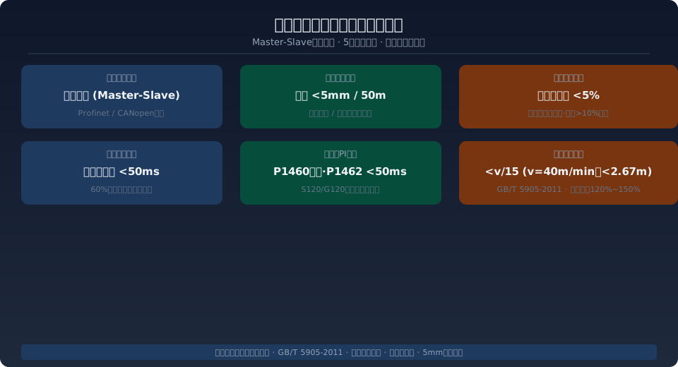
⚠️ Unsynchronized bridge travel is one of the most common field faults in gantry cranes, with roughly 60% of cases traced to mismatched brake actuation timing between the two sides. The standard requires master-slave control, with motor current deviation between sides ≤5% and displacement difference ≤20mm over a 50m travel distance. The following explains the synchronous control principle and provides a 5-step deviation adjustment method that can be executed on-site.
The crane travel mechanism of a gantry crane is typically driven by two independent variable-frequency motors, one on each side. When the motor speeds on the two sides fall out of sync, the crane bridge skews during travel. In severe cases, this leads to wheel flange wear, accelerated rail wear, and even derailment. Synchronous control of the crane bridge is the single most critical part of commissioning — it involves not just tuning a few VFD parameters, but a systematic coordination of brake linkage, encoder feedback closed-loop control, and mechanical transmission characteristics.
Root Causes of Unsynchronized Crane Bridge Travel
At its core, unsynchronized bridge travel in a gantry crane stems from a difference in linear wheel speed between the two sides. In an ideal scenario, both motors run at equal speeds, wheel diameters match, and brakes release and apply simultaneously, keeping the crane bridge moving in a straight line. In real-world operation, however, the following factors introduce speed differences between the two sides:
Mismatched VFD parameters — If the speed-loop PI parameters (P1460 proportional gain, P1462 integral time) on the two VFDs are not set identically, the actual output frequency will differ even when the same speed setpoint is applied. When the P1460 difference between the two sides exceeds 2, or the P1462 difference exceeds 50ms, synchronization error accumulates over time, reaching a displacement difference of 30–50mm after 50m of travel.
Asynchronous brake actuation — This is the most common root cause, accounting for roughly 60% of on-site synchronization faults. When the release time difference between the two brakes exceeds 50ms at startup, or the brake application time difference exceeds 50ms at stop, the side that releases first receives driving torque first, causing the crane bridge to yaw toward the opposite side. Differences in hydraulic thruster stroke on hydraulic thrust brakes, or uneven spring preload on shoe brakes, both contribute to this timing mismatch.
Encoder feedback faults — In master-slave control mode, the master drive transmits its actual speed value to the slave drive over Profinet or CANopen fieldbus as the speed setpoint. Lost encoder pulses, dropped communication frames, or loose encoder mounting all cause the slave to receive an incorrect speed command, allowing deviation to accumulate. A typical Profinet communication cycle is 2–4ms; if more than 3 consecutive cycles are dropped, troubleshooting should begin immediately.
Mechanical transmission differences — Wheel diameter differences exceeding 0.5mm between the two sides (e.g., mixing a new wheel with one that has been repeatedly re-profiled), inconsistent gear mesh clearance in the reducers, angular transmission errors caused by worn coupling elastomers, and bearing drag on one side (indicated by no-load current above 50% of rated) all translate into linear speed differences between the two sides.
Rail friction coefficient variation — When one rail is contaminated with oil or grease (friction coefficient μ=0.1–0.2) while the other remains clean (μ=0.3–0.5), the wheels on the low-friction side slip, causing the crane bridge to skew toward the high-friction side. This condition is especially common on rail sections near machine shops and lubricating oil stations.
Synchronous Control Principle for Gantry Crane Bridge Travel
Gantry crane bridge travel synchronization typically employs a master-slave control architecture. The master VFD receives a unified speed setpoint from the PLC and drives its motor through speed closed-loop control. The slave VFD does not take its setpoint directly from the PLC; instead, it receives the master's actual speed value (P2060) over the fieldbus as its own setpoint (P2070), achieving a "slave follows master" synchronization effect.
The communication link is typically Profinet RT (real-time communication, cycle 2–4ms) or CANopen fieldbus. The slave VFD must be configured for "slave follow" mode: set the speed setpoint source to fieldbus (P1000=6), set the slave to speed-follow mode (P1500=1), and set the speed follow ratio coefficient P1501=1.0 (1:1 follow).
Closed-loop correction — For applications requiring higher synchronization accuracy (e.g., nuclear power or hydropower station gantry cranes, where deviation must be ≤5mm), laser distance sensors are installed on both end carriages to detect positional deviation in real time and feed it back to the PLC. When deviation exceeds 10mm, the PLC automatically reduces the master speed to allow the slave to catch up; once deviation drops below 3mm, normal operating speed is restored. This closed-loop correction improves synchronization accuracy from ±20mm (open-loop) to ±5mm.
5-Step Deviation Adjustment Method
The following is a 5-step adjustment procedure that can be executed directly on-site, arranged from simplest to most complex. Verify the results after each step before proceeding to the next.
- Step 1: Unify VFD parameters — Confirm that the speed-loop PI parameters on both VFDs match: P1460 (proportional gain) deviation ≤2, P1462 (integral time) deviation ≤50ms. If they differ, reset both sides to factory defaults (S120: P1460=0.3, P1462=100ms), then fine-tune based on load characteristics. Also verify that the ramp-up/ramp-down times (P1120/P1121) are identical; a ramp time of 3–5s is recommended for bridge travel.
- Step 2: Check brake synchronization — The actuation time difference between the two brakes must be ≤50ms. At startup: use an oscilloscope or high-speed camera to measure the time from brake electromagnet energization to full release of the brake shoe on each side; the difference between sides must be ≤50ms. At stop: measure the time from power-off to full brake application on each side; the difference must be ≤50ms. If the time difference exceeds 100ms, the side that brakes first generates braking torque, causing the crane bridge to skew toward that side. Adjustment: for shoe brakes, adjust the spring preload compression on both sides so the braking torque difference is ≤10%; for hydraulic brakes, inspect the thruster stroke and hydraulic pipeline pressure.
- Step 3: Verify master-slave communication — Use an oscilloscope to compare the master's P2060 (actual speed value) waveform with the slave's P2070 (speed setpoint) waveform. The two waveforms should be essentially identical in amplitude and phase; a deviation of <2% is acceptable. If deviation exceeds 5%, inspect the Profinet/CANopen communication link quality (indicator status, frame loss rate) and the slave's P1000/P1500 configuration. If the slave is not correctly configured for "slave follow" mode, it will run on its local setpoint rather than the master's actual value, leaving the two sides completely independent and synchronization unachievable.
- Step 4: Measure mechanical transmission differences — Measure the no-load current of both bridge drive motors (should be in the 30%–40% of rated current range). If one side draws more than 50% of rated current, mechanical resistance on that side is abnormal — check each item in turn: wheel bearing drag (rotate the wheel by hand to feel resistance), reducer gear mesh condition (listen for abnormal noise), and coupling elastomer wear (inspect clearance). Wheel diameter difference between the two sides must be ≤0.5mm (measured with a micrometer); if it exceeds this value, the wheel must be re-profiled or replaced. Clean rail surface oil contamination with an industrial degreaser to restore a friction coefficient of ≥0.3.
- Step 5: Dynamic operation verification — Run the crane bridge back and forth at rated speed 3 times over the full rail length. Use a clamp meter to measure the current of both bridge drive motors simultaneously; a current deviation of ≤5% between sides is acceptable. Use a laser rangefinder to measure the travel distance difference between the two sides; a displacement difference of ≤20mm over a 50m travel distance is acceptable. If these criteria are not met, return to Step 1 and re-check each item systematically. For applications requiring higher accuracy, install laser distance sensors for closed-loop correction, which can hold synchronization deviation within ±5mm.
Key Technical Parameters for Synchronization Commissioning
Kelude Heavy Industry: Overhead Crane & Gantry Crane Manufacturer
Kelude Heavy Industry is a professional manufacturer of overhead cranes, gantry cranes, and electric hoists. With over 20 years of experience in the material handling industry, we provide reliable lifting solutions for workshops, warehouses, and industrial facilities across the United States and Europe.
Frequently Asked Questions
Q: What is the typical lead time for a standard overhead crane?
A: For standard models, lead time is typically 4-6 weeks after order confirmation. Customized cranes may require 8-12 weeks depending on complexity.
Q: Do you provide installation services overseas?
A: Yes, we offer turnkey installation services in the US and Europe. Our technicians can supervise installation or provide training for your local team.
Q: Can your cranes be adapted for explosion-proof environments?
A: Absolutely. We offer explosion-proof options for motors, controls, and lighting, compliant with ATEX and IECEx standards, suitable for hazardous areas.
Q: What is the warranty period for your products?
A: We provide a standard 12-month warranty covering parts and workmanship. Extended warranties are available upon request.
Q: How do you ensure crane safety and compliance?
A: All our cranes are designed and manufactured in accordance with ISO 4301, ISO 12480, and IEC 60204-32. Each crane undergoes rigorous load testing and quality inspection before shipment.
Relevant Standards and Code Basis
A: Gantry crane bridge synchronization involves multiple national standards and industry specifications. Commissioning and acceptance work should reference the following standards:
Braking distance requirements for the crane travel mechanism are based on ISO 4306 — Crane Test Code Interpretation, which specifies a braking distance of ≤ v/15 (i.e., ≤2.67 m at a rated speed of 40 m/min), with braking torque recommended at 120%–150% of the rated value. General design requirements and safety specifications for gantry cranes reference ISO 4306-1 — General-Purpose Gantry Crane, Part 1, covering drive configuration, synchronization accuracy, and inspection methods for the crane travel mechanism.
Design and safety requirements for the electrical control system are based on IEC 60204-32 — Interpretation of Electrical Control Equipment for Cranes and IEC 61508 — Functional Safety of Electrical/Electronic/Programmable Electronic Safety-Related Systems. IEC 60204-32 defines functional requirements and test methods for crane electrical control equipment, while IEC 61508 specifies safety integrity level (SIL) requirements for safety-related electrical, electronic, and programmable electronic systems. When bridge synchronization involves a safety PLC and Profisafe communication, the system must meet SIL 2 or higher safety integrity.
During bridge synchronization commissioning, both drive motors must meet the specified braking distance under full-load braking conditions. Consistent brake actuation timing on both sides is the fundamental prerequisite for synchronization.
In practice, Kelude's gantry cranes come standard with a master-slave VFD drive configuration. Both sides undergo unified PI parameter calibration for the speed loop and brake synchronization verification before leaving the factory, so on-site commissioning typically requires only minor adjustments based on rail surface conditions.
Gantry Crane Bridge Synchronization FAQ
Q: What is the most common cause of bridge travel mismatch on a gantry crane?
A: Approximately 60% of mismatch cases are caused by inconsistent brake actuation timing between the two sides. If the difference in brake release time or brake application time exceeds 50 ms, the side that acts first creates an unbalanced torque that causes the crane bridge to skew. Troubleshooting should start by checking brake clearance (0.5–1.5 mm per side for block brakes, with a maximum difference of 0.3 mm between sides) and braking torque settings (maximum 10% difference between sides), followed by verifying the consistency of VFD speed loop PI parameters.
Q: What synchronization accuracy can master-slave control achieve, and how does it compare to independent control?
A: Open-loop master-slave control achieves synchronization accuracy of ±20 mm over a 50 m travel distance. Adding a laser distance sensor with closed-loop correction improves accuracy to ±5 mm. The key advantage of master-slave control is that the slave drive directly tracks the master's actual speed value rather than each drive independently following the PLC setpoint, eliminating cumulative errors caused by differences in VFD response. In independent control mode, each VFD regulates its own speed loop separately, so deviations continue to accumulate under asymmetric loads or varying rail conditions.
Q: What should be done if the bridge braking distance exceeds the limit, and what braking torque should be set?
A: Per ISO 4306-2011, the bridge braking distance must not exceed v/15 (where v is the rated travel speed in m/min) — ≤2.67 m at 40 m/min and ≤1.33 m at 20 m/min. Braking torque should be set to 120%–150% of the rated value by adjusting the brake spring preload compression. If the braking distance is too short (excessive braking torque), the crane bridge will stop with severe oscillation and impact at rail joints; if too long, there is a collision risk. After brake adjustment, a dynamic load test should be performed at rated load to verify performance.
Q: Can an older gantry crane without Profinet fieldbus still achieve master-slave synchronization control?
A: Yes. VFDs without fieldbus connectivity can implement simplified master-slave control using analog signals: the master drive's analog output (AO) terminal sends the actual speed signal (0–10V / 4–20mA) to the slave drive's analog input (AI) terminal as the speed reference. This approach offers slightly lower accuracy than a digital bus (approximately ±30 mm over 50 m), but it keeps hardware costs low and is well suited for retrofitting older equipment. Kelude can supply a complete analog-based master-slave retrofit package for your VFDs, with a typical installation time of 3–5 working days. After calibration, synchronization accuracy meets all standard operating requirements.
All Kelude gantry cranes come standard with an electrical control system and factory-calibrated master-slave synchronization, ready for plug-and-play operation on site.
