

Overhead Crane Digital Twin: 3D Modeling & Real-Time Data
The core of an overhead crane Digital Twin lies in the engineering execution of three key stages: 3D modeling, real-time data mapping, and virtual-physical synchronization. This article provides an in-depth breakdown of the complete data chain—from architecture design to technology selection—covering the data acquisition layer, twin modeling layer, and application layer. It details critical technologies including the AAS data model, kinematic/dynamic simulation, rigid-flexible coupling analysis, and WebGL rendering, offering a systematic summary of lessons learned from real-world Digital Twin deployments.
Digital Twin for Overhead Crane has generated significant buzz over the past two years, yet few projects have moved beyond the pilot stage. The reason is straightforward—every step presents its own set of challenges: how to build the 3D model, how to map real-time data, and how to keep the virtual and physical worlds in sync. This article is not a conceptual overview; it breaks down the technical details of overhead crane Digital Twin implementation, from system architecture to engineering execution. Our team encountered numerous pitfalls during deployment, so consider this a field guide based on hands-on experience.
Overhead Crane Digital Twin: System Architecture Explained
An overhead crane Digital Twin system, in essence, creates a virtual mirror of each physical crane that stays synchronized in real time. This mirror is not just a visual replica (3D model)—it moves (real-time pose synchronization), computes (simulation and prediction), and remembers (historical playback).
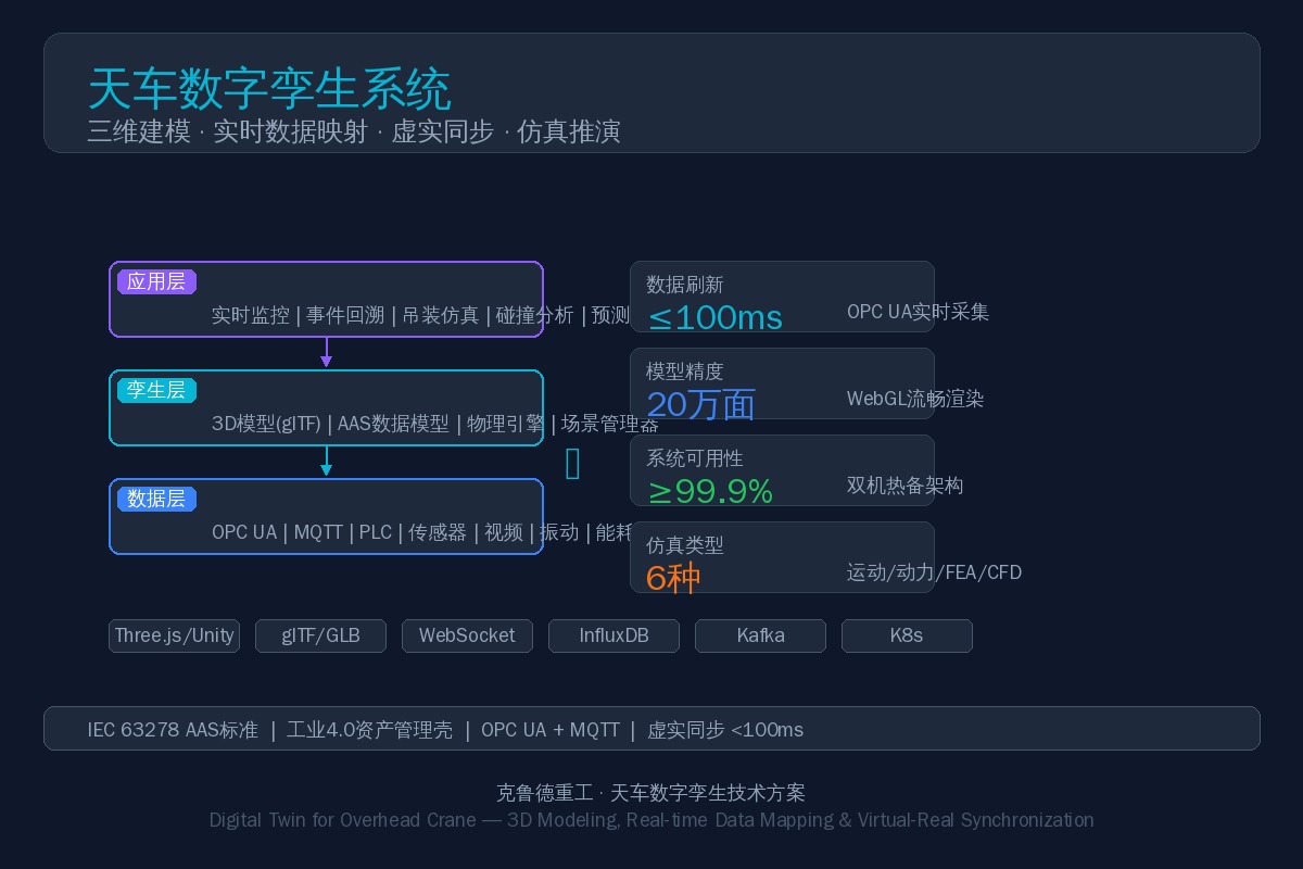
A complete Digital Twin system is structured in three layers:
1.1 Data Acquisition Layer
This is the foundation of the Digital Twin. PLC real-time data, sensor signals, video streams, vibration spectra, and energy consumption data—all information from the physical world must enter the digital space through a unified protocol channel. The core protocol is OPC UA (IEC 62541), which provides downward compatibility with industrial protocols such as Siemens S7, Modbus TCP/RTU, and PROFINET, while exposing a unified data interface upward. The acquisition cycle can be as fast as 100 ms.
1.2 Twin Modeling Layer
This layer transforms raw data into something "visible." It includes the 3D geometric model (rendered with WebGL), a kinematic skeleton system (parent-child hierarchy of crane bridge, trolley, and hoist), the AAS (Asset Administration Shell) data model (describing the equipment's full lifecycle information per IEC 63278), and a physics engine (handling wire rope oscillation, collision detection, and other physical behaviors).
1.3 Application Layer
This layer feeds twin data into specific business scenarios: real-time monitoring screens, 3D fault event replay, hoisting path pre-simulation, collision analysis, predictive maintenance, and remote operation assistance.
Related reading: Structural Health Monitoring System—In our deep dive on overhead crane Digital Twin technology, we discussed the engineering implementation of 3D modeling and virtual-physical synchronization. A structural health monitoring (SHM) system builds on the Digital Twin foundation by adding real-time strain monitoring and fatigue life assessment, closing the loop from "seeing" the asset to "measuring" it accurately.
3D Modeling and Scene Construction for Crane Digital Twins
2.1 Model Sources and Formats
The 3D model of an overhead crane can be exported directly from the design BOM and STEP files. The recommended format is glTF/GLB (GL Transmission Format), the Web-based 3D transmission standard developed by Khronos, with native support for PBR materials (physically based rendering). It loads directly in browsers without any plugins. A single crane model is approximately 50 MB (around 200,000 triangles), and with LOD (Level of Detail) progressive loading, it runs smoothly in the browser.
Factory environment models (crane rails, columns, production line equipment, etc.) typically come from BIM (Building Information Modeling) or 3D laser point cloud scanning. These datasets are large (around 1 million triangles), so mesh decimation during preprocessing is recommended, along with Octree scene partitioning for visibility culling.
2.2 Coordinate System Calibration
Virtual-physical synchronization requires a one-to-one correspondence between coordinates in the virtual space and the physical space. The engineering approach uses a "three-step calibration method":
- Coarse calibration: Establish the global coordinate system of the scene based on the BIM model or factory CAD drawings (typically using factory columns as reference points).
- Fine calibration: Use laser distance sensors or a UWB positioning system on the crane to capture real-time 3D coordinates (X/Y/Z) of the crane bridge, trolley, and hoist, and feed them into the virtual scene to drive the model.
- Dynamic compensation: Account for long-term drift factors such as rail settlement and thermal deformation by performing automatic calibration periodically (recommended monthly).
Real-Time Data Mapping and the AAS Data Model
3.1 Data Flow Architecture
| Layer | Technology / Protocol | Function |
|---|---|---|
| Edge Gateway | OPC UA Client / MQTT | Aggregates PLC and sensor data, protocol conversion, time stamping |
| Real-Time Data Bus | Kafka / MQTT Broker | Message queuing, publish-subscribe, data buffering |
| Digital Twin Engine | Unity / Three.js + Physics Engine | 3D rendering, pose update, collision detection, simulation execution |
| Data Storage | Time-Series DB + Relational DB | Historical data archiving, event logging, analytics |
| Cloud Platform | REST API / Web Socket | Remote access, multi-crane management, data analytics |
Two critical performance indicators on this data path:
- Data acquisition latency: From PLC register change to 3D engine pose update, the target is ≤200 ms.
- Data throughput: A single crane has approximately 200 data points at a 100 ms cycle; one server supports concurrent operation of 50+ cranes.
3.2 AAS (Asset Administration Shell) Data Model
AAS is the core data standard of Industry 4.0 (IEC 63278). It organizes all data into standardized "sub-model" structures:
| Sub-Model | Typical Content |
|---|---|
| Nameplate | Manufacturer, model, rated load, span, hoisting height, serial number |
| Operational Data | Real-time load, motor current, speed, position, temperature |
| Maintenance History | Inspection records, component replacements, repair logs |
| Health Status | Fatigue life consumption, structural deformation, remaining useful life |
| Simulation Results | Path interference reports, dynamic response, FEA stress distribution |
The key advantage of this model is standardization—ERP, MES, SCADA, and cloud platforms can all read and understand the crane's full lifecycle data through a unified interface, eliminating data format compatibility issues.
Crane Digital Twin Simulation: Kinematics, Dynamics, and FEA
The fundamental difference between a Digital Twin and a standard 3D monitoring system is that a Digital Twin does more than "see"—it "computes." Simulation capability is the core value proposition of a Digital Twin.
4.1 Kinematic Simulation
Before executing a new hoisting task, the path is first run through the twin environment to verify that the combined motion of the crane bridge, trolley, and hoist is free of interference. Inputs are the 3D model and motion trajectory; the output is a path interference report. A single simulation run takes approximately 1–5 minutes and runs on a standard PC.
4.2 Dynamic Simulation
This analyzes dynamic parameters such as inertial forces during acceleration and deceleration, wire rope swing angle, and braking distance. The core task is building a multi-body dynamic model of the crane (main girder, trolley, suspended load, and wire rope as four rigid bodies plus flexible bodies), solved using Lagrange's equations of motion.
4.3 Finite Element Analysis (FEA)
Primarily used for structural strength verification and fatigue life assessment. Typical parameters:
- Element type: Shell181 shell elements (suitable for thin-walled structures)
- Mesh size: 20 mm (main girder) / 10 mm (refined at weld seams)
- Material: Q355B (≈S355JR), E = 206 GPa, ν = 0.3
- Load cases: rated load of 320 kN at mid-span + eccentric load at 0.5 m offset
- Outputs: maximum stress, maximum displacement, safety factor
4.4 Rigid-Flexible Coupling Simulation
The wire rope is the most challenging component to simulate—it is both a flexible body (subject to tension, bending, and torsion) and a connector to the rigid suspended load. The standard engineering approach uses a discretized rope model (dividing the wire rope into N rigid segments connected by spring-damper elements), combined with a rope-pulley contact algorithm to simulate the winding and unwinding of the rope on the drum. RecurDyn delivers the best performance for this type of simulation.
Key Technology Selection for Digital Twin Platforms
Selecting the key technology components for a Digital Twin platform requires balancing performance, ecosystem maturity, and cost:
| Technology Component | Recommended Solution | Alternative Solution | Description |
|---|---|---|---|
| 3DEngine | Three.js | Unity3D | Web Portable; Unity High-Fidelity |
| Model Format | g ITF/GLB | FBX/OBJ | Web Standard+PBRMaterial |
| Real-Time Communication | Web Socket+MQTT | g RPC | Bidirectional Low Latency |
| Time-Series Database | Influx DB | Timescale DB | High Write Throughput |
| Physics Engine | Cannon.js | Phys X | Sway/Collision Simulation |
| Message Broker | Kafka | Rabbit MQ | High-Throughput Device Data Stream |
| Cloud Deployment | K8s+Docker | — | Microservices+HPA |
6. Typical Application Scenarios
6.1 Real-Time 3D Monitoring
Dispatchers open a 3D scene in their browser and instantly see the live status of every overhead crane — which one is hoisting, which is idle, which has triggered an alarm, the current load percentage, and the exact position of each unit. Compared with traditional flat monitoring interfaces built on lists and trend curves, the 3D view delivers a level of situational awareness that is simply in a different league.
6.2 3D Event Replay for Fault Analysis
When an overhead crane malfunctions, the conventional approach is to dig through PLC logs and decode fault codes — abstract and unintuitive. A Digital Twin lets you replay the 30 seconds leading up to the fault in full 3D: how the crane bridge moved, how the load swung, which sensor tripped first. Every detail can be re-enacted in the twin environment, which is invaluable for incident analysis and liability determination.
6.3 Hoisting Path Pre-Simulation
When a new batch of workpieces needs to be moved from point A to point B, with production equipment and columns in the way, the operator first enters the hoisting task into the twin environment. The system automatically plans the optimal path and runs a pre-simulation, flagging any interference points for immediate adjustment — eliminating the awkward "we can't get through halfway through the lift" scenario.
6.4 Collision Analysis
When multiple overhead cranes operate in the same bay, spatial interference is a constant risk. The Digital Twin calculates the safety envelope of every crane in real time and triggers an alarm — or even an interlocked stop — when any two envelopes approach a critical threshold. Unlike traditional mechanical limit switches or laser-based anti-collision systems, the Digital Twin's key advantage is that it predicts rather than merely reacts after contact has already occurred.
7. Key Engineering Implementation Considerations
- Network infrastructure is the critical bottleneck: Real-time data at 100 ms intervals places significant demands on the industrial network. The segment from the fieldbus (PROFINET/EtherCAT) to the OPC UA server must be gigabit wired Ethernet. For the link from OPC UA to the cloud or local server, an industrial 5G private network or fiber optic connection is recommended to avoid data packet loss caused by WiFi interference.
- Historical data storage strategy: At one record every 100 ms, a single crane generates roughly 170,000 records per day. A tiered downsampling approach is recommended — raw data retained for 7 days, minute-aggregated data for 90 days, and hour-aggregated data retained permanently.
- Model maintenance must keep pace: If a crane undergoes a retrofit (adding attachments, replacing the hoisting mechanism, rail alignment, etc.), the twin model must be updated accordingly. We recommend integrating model management into the equipment change management process — no model update, no go-live.
- Keep the UI restrained: A rich 3D scene can easily become a showcase of visual effects, but the bottom line for industrial applications is information clarity. Color coding must carry clear semantics (green for normal, yellow for warning, red for fault) — avoid unnecessary reflections or glow effects that serve aesthetics rather than function.
Conclusion
The Digital Twin for overhead cranes is not a decorative new concept — it is an essential step in the evolution from "brute-force lifting equipment" to "intelligent machinery." This article is by no means the end of the discussion — every technology mentioned here deserves deeper exploration. We have since published A Complete Engineering Implementation of the AAS Data Model, Simulation Model Parameter Calibration Methods, and Edge-Side Real-Time Rendering Optimization. Colleagues with related needs are welcome to follow along.
Further reading: AI Weld Inspection System — the overhead crane Digital Twin system delivers 3D visualization of equipment operating status. If weld seam defect data from the fabrication stage is entered into the Digital Twin platform, SHM monitoring during service life can be correlated with factory quality data for combined analysis.
Frequently Asked Questions
Q: What hardware investment does an overhead crane Digital Twin require?
A: The minimum configuration includes an OPC UA gateway (approximately $740), an industrial PC (approximately $1,180), and a sensor suite (approximately $2,220 per crane). If the factory already has PLC and SCADA systems in place, only an OPC UA gateway needs to be added for integration — the retrofit cost is very low.
Q: What is the difference between a Digital Twin and traditional SCADA?
A: SCADA provides schematic diagrams with trend curves; a Digital Twin offers real-time 3D synchronization with simulation and prediction. SCADA tells you the motor temperature is 85°C. The Digital Twin tells you the motor temperature is 85°C, it is located at position 3 in Zone B of the factory building, it will exceed the limit in 15 minutes at the current trend, and maintenance should be scheduled in advance. The information density is not in the same league.
Q: How many overhead cranes can a single server manage?
A: A standard configuration (i7 + GTX1650) supports concurrent rendering with LOD switching for 15 cranes. If the server is only used for data acquisition without 3D scene rendering, a single server can support over 100 cranes.
