Crane Rail Gnawing: 6 Common Faults, Causes & Wheel Track Correction
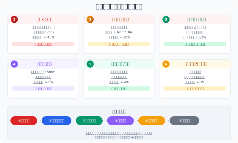
Key Point Crane rail gnawing refers to abnormal friction between the wheel flange and the rail side during crane operation, causing accelerated flange wear, increased running resistance, abnormal noise, and in severe cases, derailment. Six major causes ranked: ① Wheel-to-rail center deviation (45%); ② Rail straightness out of tolerance (30%); ③ Unsynchronized driving wheels on both sides (12%); ④ Uneven wheel wear (6%); ⑤ Crane bridge chassis frame deformation (4%); ⑥ Loose rail clamps / rail creep (3%). Rail gnawing diagnosis should follow the sequence: visual inspection → rail measurement → wheel flange inspection → diagonal measurement → braking synchronization check. Kelude Heavy Industry offers on-site rail gnawing diagnosis services.
Symptoms and Consequences of Rail Gnawing
Rail gnawing is one of the most common faults in crane operation. Typical symptoms include a distinct "squealing" friction sound during travel, shiny polished areas on the wheel flange, wear marks on the rail side, increased running resistance that drives up motor current, and in severe cases, flange edge deformation or cracking. Loose rail clamps are also frequently triggered by vibration from rail gnawing. Based on Kelude's analysis of after-sales field data, approximately 68% of on-site maintenance requests are related to rail gnawing. Early diagnosis can prevent flange cracking and derailment accidents.
| Rail gnawing (wheel flange rubbing)Degree | flange wear Quantity | Operating Performance | Handling Method | Handling Cost |
|---|---|---|---|---|
| Light | <2mm | Occasional Abnormal noise, Current Normal | adjustment Rail Clamp / Rail Clip+Lubrication | 200~800CNY |
| Moderate | 2~5mm | Continuous Abnormal noise, Current Slightly High | adjustment Wheel Block+Crane Rail Correction | 1000~3000CNY |
| Severe | >5mm Or Edge Curling | Severe Vibration Abnormal noise, Body Vibration | replacement Crane wheel+Comprehensive Crane Rail Correction | 5000~15000CNY |
Rail Gnawing: Six Root Causes and Troubleshooting Methods
① Wheel-to-Rail Centerline Misalignment (45%)
When the centerlines of the four crane wheels do not align with the rail centerline, the wheel flanges remain in constant contact with the rail side. The crane gnaws one side when traveling in one direction and the opposite side when reversing. Kelude recommends the diagonal measurement method: measure the intersection points of the diagonals formed by the four wheels; each point deviation should be ≤5mm. The adjustment method involves adding shims between the wheel bearing housing and the end carriage, with each adjustment step of 0.5–1mm, gradually correcting until gnawing is eliminated.
② Rail Straightness Out of Tolerance (30%)
Rail curvature or joint misalignment forces the wheels to deflect as they pass. FEM 1.001 requires rail straightness of ≤±3mm per 10m. Periodic abnormal noise occurs when wheels pass over locally curved sections. Use a Laser Distance Sensor or the string line method for detection, and correct curved sections by adjusting the Rail Clamps. Each adjustable clamp plate provides approximately 3mm of adjustment stroke.
③ Asynchronous Driving Wheels on Opposite Sides (12%)
Differences in drive motor speed or inconsistent brake release/engagement timing between the two sides cause the crane bridge to yaw during startup or stopping. Kelude recommends verifying that motor rated speeds match and brake gaps are equal (standard 0.6–1.5mm). Adjust the brake release distance to equalize Braking torque on both sides.
④ Uneven Wheel Wear (6%)
After years of service, a tread surface diameter difference of >0.5mm among the four wheels causes speed variation within each wheel revolution. A diameter difference of >0.2mm between two wheels on the same side is sufficient to trigger rail gnawing. Measure the Wheel Diameter of the tread surface; if deviation exceeds 0.5mm, restore by Turning or replace. Kelude offers on-site tread surface Turning services.
⑤ Main Girder Deformation / Eccentric Loading (4%)
Main girder deflection or end carriage deformation results in uneven wheel load distribution. Measure the camber of main girder (standard: 1/1000 to 1.5/1000 of the Span); correction is required if camber is lost or becomes negative. If wheel load difference exceeds 20%, reposition the Trolley or reinforce the structure.
⑥ Loose Clamps / Rail Creep (3%)
Loose Rail Clamp bolts allow longitudinal rail displacement (creep), which enlarges or deforms rail joints. Inspect the rail joint gap (standard 4–8mm) and retighten clamp bolts to the specified Torque.
Rail Gnawing Inspection and Precautions
Rail Gnawing Correction: Step-by-Step Procedure
Step 1: Measurement & Diagnosis (0.5 day) — Use a laser distance sensor to measure rail straightness (standard: ≤3 mm per 10 m), check wheel position deviation across all four wheels using the diagonal method (standard: ≤5 mm), and use a clamp meter to compare drive motor current draw on both sides (a deviation >10% indicates braking synchronization issues).
Step 2: Rail Alignment (1–2 days) — Adjust rail clamps segment by segment based on measurement results. For a single bent section with <5 mm deviation, loosen the clamps in that section, use a jack to push the rail back into alignment, then retighten and re-measure. For joint misalignment, loosen the four clamps on both sides of the joint, shim the joint level, and retighten. Re-check straightness immediately after each adjustment.
Step 3: Wheel Block Adjustment (0.5–1 day) — Correct wheel skew by adding shims between the bearing housing and the end carriage. For horizontal skew, add shims to the left or right side of the bearing housing (each 0.5 mm shim shifts the wheel approximately 0.3 mm horizontally); for vertical skew, adjust the top and bottom shims on the bearing housing. Make adjustments in 0.5–1 mm increments, then run a no-load test to confirm the correction.
Step 4: Brake Synchronization (0.5 day) — Check brake release gap on both sides (standard: 0.6–1.5 mm) and the release time difference (≤0.1 s). Adjust brake spring compression so that braking torque is consistent on both sides. Kelude's on-site rail gnawing service follows this four-step process; severe cases include wheel replacement and full rail realignment.
Daily Maintenance Points to Prevent Rail Gnawing
Every shift: Listen for abnormal noise during operation (distinguish between periodic and continuous sounds), visually inspect the bright wear marks on wheel flanges for position changes, and record ammeter readings.
Monthly: Check rail clamps for loosening (torque-check 10% with a torque wrench), measure rail straightness in critical areas (joints, weld seams), and inspect wheel flange wear.
Quarterly: Compare diagonal wheel measurements (the intersection point deviation of the four diagonal lines should be ≤5 mm), verify that motor speeds match on both sides (measure running current with a clamp meter), and test brake release gap and synchronization.
Annually: Perform a full runway survey and log the data to build a trend record, measure wheel tread diameter (difference between two wheels on the same axle ≤0.2 mm), and re-check the camber of the main girder. Kelude offers annual runway survey services that include laser distance measurement reports and maintenance recommendations.
FAQ
Q: Where does rail gnawing most commonly occur?
A: Most commonly on the inner side of the driving wheel flange rubbing against the rail side. Since the driving wheels transmit the traction force, gnawing is most pronounced when the wheels are skewed. It is also most severe during startup and braking due to inertia forces.
Q: How can I quickly diagnose the cause of rail gnawing myself?
A: Use this three-step diagnosis: ① Check the bright wear marks on the flanges — marks on both sides suggest a rail problem, while marks on one side only point to wheel misalignment; ② Listen to the noise pattern — periodic noise matching the rail joint spacing indicates a rail issue, while a continuous high-pitched squeal suggests wheel misalignment; ③ Measure rail straightness — use a steel ruler or the string line method to check for bent sections. Kelude also offers on-site rapid diagnosis with a laser distance sensor.
Q: Can rail gnawing cause derailment?
A: Mild rail gnawing does not directly cause derailment, but severe, long-term gnawing (flange curling or cracking) significantly increases the derailment risk. Per ISO 4301 Crane Design Standard, flanges must be replaced when wear reaches 50% of the original thickness. Kelude recommends scheduling correction within one month of detecting moderate or severe gnawing.
Q: What is the relationship between rail creep and rail gnawing?
A: Rail creep (slow longitudinal displacement of the rail) is one of the contributing factors to rail gnawing. Creep changes the rail joint gap and compromises straightness, which in turn triggers gnawing. Loose clamps or insufficient preload are the main causes of creep. Kelude recommends installing clamps at closer spacing (200–300 mm) near rail joints and re-tightening them six months after installation.
This completes the full guide to overhead crane rail gnawing — covering cause analysis, diagnosis, and corrective procedures. Kelude offers on-site rail gnawing diagnosis (laser distance measurement + wheel block adjustment + rail alignment) with response within 48 hours. For rail gnawing issues, please contact the Kelude after-sales technical team.