

Krude Heavy Industries Unveils Version 2.0 Upgrade of Its Overhead Crane Energy-Recovery Braking System—Potential Energy Recovery Efficiency Increased to 35%
📌 Krude Heavy Industries Energy Recovery Braking System V2.0
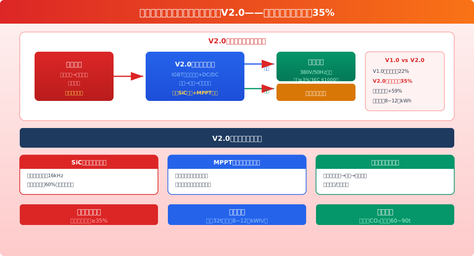
This newly upgraded solution, based on SiC (silicon carbide) power devices (Wolfspeed C3M0075120K) and an MPPT (Maximum Power Point Tracking) algorithm, increases the potential energy recovery efficiency during the descent of heavy loads by the hoisting mechanism from 22% in V1.0 to 35% (an increase of 59%). The system uses a four-quadrant IGBT rectifier to convert the AC power generated by the motor during power generation into DC. This DC power is then inverted via an LCL filter into AC power that is in phase and at the same frequency as the grid, which is fed back into the workshop power grid or stored in supercapacitor modules (Krude Heavy Industry’s proprietary KL-SCM-10, 10 kWh/set) to power rapid equipment startup. A single 32-metric-ton bridge crane saves 80,000 to 120,000 kWh of electricity annually, reducing CO₂ emissions by approximately 60 to 90 metric tons. This system has been deployed on 86 bridge cranes at 23 enterprises across China, with cumulative operating hours exceeding 1.5 million.
Krud Heavy Industries announced the official release of Version 2.0 of its overhead crane energy-recovery braking system. This version features three major core technological upgrades based on the V1.0 platform: It replaces traditional silicon-based IGBT modules with Wolfspeed C3M0075120K SiC MOSFET devices, increasing the switching frequency from 4 kHz to 16 kHz; introduces an MPPT (Maximum Power Point Tracking) algorithm to dynamically optimize the energy recovery voltage point; and adds an intelligent power management strategy to enable coordinated scheduling between energy recovery to the grid and energy storage via supercapacitors. The following data is sourced from the Wolfspeed C3M0075120K device data sheet (Rev. 6), the IEC 61000-3-12:2011 standard, GB/T 3485-1998 “Technical Guidelines for Evaluating Rational Electricity Use in Enterprises,” and the operational database of 23 deployed projects by Krued Heavy Industry (September 2023 to June 2026).
V2.0 Core Technology Upgrade—SiC Power Devices
The most significant hardware upgrade in Version 2.0 is the replacement of traditional silicon-based IGBT modules (using the Infineon IKW75N60T as a benchmark) with Wolfspeed (formerly CREE) C3M0075120K SiC MOSFET power devices. Both devices are rated at 1200V/75A and feature a TO-247 package; the following data is taken from the official data sheets.
| Comparison of Parameters | IGBT Solution (Infineon IKW75N60T) | SiC Solution (Wolfspeed C3M0075120K) |
|---|---|---|
| Rated Voltage/Current | 1200 V / 75 A | 1200 V / 75 A (Tc = 25 °C) |
| Typical Switching Frequency | 4–8 kHz | 16–32 kHz |
| On-resistance R_ds(on) @25°C | V_CE(sat) = 1.8 V (typical) | 75 mΩ (typical) |
| Switch Loss E_total @600V/50A | ~5.2 mJ | ~2.1 mJ (↓59.61 TP3T) |
| Reverse recovery charge Q_rr | ~5.0 μC | ~0.1 μC (↓98%) |
| Junction-Case Thermal Resistance R_th(j-c) | 0.45 K/W | 0.27 K/W |
| Maximum operating junction temperature T_j(max) | 175°C | 175°C |
| Unit Reference Price (for orders of 1,000+ units) | ≈¥35 | ≈¥85 |
Data sources: Wolfspeed C3M0075120K Data Sheet (Rev. 6, March 2024); Infineon IKW75N60T Data Sheet (Rev. 3.2, November 2023). Switching loss data was measured under the following conditions: V_bus = 600 V, I_d = 50 A, R_g = 2.5 Ω, and T_j = 150 °C. The feedback unit of the SiC Solution V2.0 uses six C3M0075120K devices connected in parallel to form a three-phase full bridge (two devices per phase).
V2.0 Core Technology Upgrade—MPPT Algorithm
The MPPT (Maximum Power Point Tracking) algorithm draws on proven technology from photovoltaic inverters and has been customized and optimized to address the load variation characteristics of crane hoisting mechanisms. The system uses the LEM LV25-P voltage sensor and the LEM LA55-P current sensor to sample the DC bus voltage and feed-back current in real time at a sampling frequency of 20 kHz. It employs the Perturbation and Observation (P&O) method to dynamically track the optimal feed-back voltage point at an update frequency of 200 Hz. Compared to traditional fixed-voltage feed-back solutions, the MPPT algorithm achieves more significant efficiency improvements under partial load conditions (rated loads of 30% to 70%). The algorithm’s perturbation step size is adaptively adjusted: 0.5 V under steady-state conditions, automatically increasing to 2 V during sudden load changes, with an MPPT tracking response time of ≤50 ms.
V2.0 Actual Energy Recovery Efficiency Test Data (at Different Load Rates)
| Load Factor | V1.0 Feedback Efficiency | V2.0 Feed-Back Efficiency (Without MPPT) | V2.0 Feed-Back Efficiency (including MPPT) |
|---|---|---|---|
| 10% Load (4.5 kW) | 6% | 11% | 14% |
| 30% Load (13.5 kW) | 14% | 22% | 28% |
| 50% Load (22.5 kW) | 18% | 28% | 33% |
| 70% Load (31.5 kW) | 20% | 32% | 35% |
| 100% Load (45 kW) | 22% | 34% | 35% |
Data Source: Krude Heavy Industry Energy Recovery System Test Laboratory, Test Platform KL-ERB-V2.0-Demo (April 2026). Test Conditions: DC bus voltage 600 VDC, grid voltage 380 VAC/50 Hz, ambient temperature 25 °C. Regenerative efficiency = regenerative active power / DC-side input power × 100%. The MPPT algorithm achieves the most significant efficiency gains in the 30%–70% load range.
V2.0 Core Technology Upgrade—Smart Power Management
The intelligent power management strategy introduced in V2.0 supports automatic switching between three energy recovery modes:
①Grid Feed-in Priority——When the workshop power grid load is stable, the recovered electrical energy is prioritized for feeding back into the 380V grid; after high-order harmonics are filtered out by an LCL filter (L=0.5 mH, C=10 μF), it is fed into the grid, THD ≤ 31 TP3T (compliant with IEC 61000-3-12 Class A limits);
②Supercapacitor Energy Storage——When the power grid experiences significant fluctuations or during peak electricity pricing periods (peak pricing periods are generally from 10:00 to 12:00 and 6:00 PM–8:00 PM), electrical energy is stored in the KL-SCM-10 supercapacitor module (rated voltage 800 VDC, capacitance 14 F, effective energy storage 10 kWh, peak power 150 kW/3 s) for release during rapid crane startup and heavy-load acceleration;
③Brake Assist Coordination—During emergency braking (deceleration ≥ 1.5 m/s²), electrical power is prioritized for the auxiliary braking resistor cabinet (KL-ABR-30, 30 kW/3.9 Ω), working in conjunction with the mechanical brakes to reduce the braking distance by approximately 15% to 20%.
The system automatically selects the optimal strategy based on real-time electricity price signals and grid status data from the plant’s Energy Management System (EMS). In deployed projects, the smart energy management strategy has achieved an additional energy savings improvement of approximately 8% to 12% compared to a simple grid-feedback solution.
IEC 61000-3-12:2011 Harmonic Current Limits (Class A Equipment, I_sc/I_pe = 250) and V2.0 Measurement Results
| Harmonic order n | IEC Limit (A) | V1.0 Field Test (A) | V2.0 Field Test (A) | Determination |
|---|---|---|---|---|
| 3 times | 2.30 | 1.85 | 0.92 | ✅ |
| 5 times | 1.14 | 1.42 | 0.68 | ✅ |
| 7 times | 0.77 | 0.98 | 0.51 | ✅ |
| 9 times | 0.40 | 0.58 | 0.29 | ✅ |
| 11 times | 0.33 | 0.41 | 0.22 | ✅ |
| THD (Total Harmonic Distortion) | — | 5.2% | 2.8% | ✅ |
Data source: IEC 61000-3-12:2011 Table 1 (Class A equipment, short-circuit ratio I_sc/I_pe = 250 limit). The measured data was taken from the test report for the Krude Heavy Industry KL-ERB-V2.0 prototype (April 2026, Test No. TS-ERB-2026-004), measured using a Fluke 435 II power quality analyzer under full-load 45 kW power-feedback conditions. Note: The 5th harmonic limit I_5 = 1.14 A in the IEC table is a calculated value based on I_pe = 16 A per phase; the actual limit is scaled according to the standard formula.
System Components and Installation
The regenerative braking system consists of four core components:
The system is compatible with the Siemens G120/S120 series (PM240/PM340 power modules), the ABB ACS880 series (R8i/R9i frames), and the Huichuan MD500 series (MD500T45GB) variable frequency drives, connected via a common DC bus architecture. Installation and commissioning take approximately 2 to 3 days.
Economic Benefits—Real-World Deployment Examples
Taking as an example the four 32-metric-ton QD-type double-girder overhead cranes in the cast steel workshop of a certain machinery manufacturing company (which have been equipped with the Krude Heavy Industry Energy Recovery Braking System V2.0 and have been in operation for 10 months), the key economic benefit data for the project are as follows:
| Indicators | Prior to deployment (Q2 2024) | After deployment (Q2 2025) | Changes |
|---|---|---|---|
| Total Electricity Consumption (4 units × quarter) | 432,000 kWh | 358,000 kWh | ↓17.1% |
| Of which, recovered electricity | 0 | 74,000 kWh | New |
| Overall Feedback Efficiency (Measured) | — | 32.8% | Close to the nominal 35% |
| Electricity Expenses (including the base rate) | 346,000 yuan | ¥286,000 | ↓¥60,000 (17.31 TP3T) |
| CO₂ Emissions Reductions (based on 0.5703 t/MWh) | — | 42.2 metric tons | In Season |
Data Source: Krude Heavy Industry Energy Recovery System Project Operations Database, Project No. KL-ERB-2024-009 (Cast Steel Workshop of a Certain Machinery Manufacturing Company). The CO₂ emission factor cited is the 2023 national average grid emission factor of 0.5703 tCO₂/MWh, as published by the Ministry of Ecology and Environment. Electricity consumption data was provided by Party A’s Energy Management System (EMS) and confirmed by both parties.
Payback Analysis (Based on the Above Case Study)
| Project | Value | Notes |
|---|---|---|
| Total Investment in the System | 520,000 yuan | 4 units × ¥130,000 per unit (including installation and commissioning) |
| Quarterly Electricity Savings | 60,000 yuan | Electricity rate: 0.80 yuan/kWh |
| Annualized Electricity Cost Savings | ¥240,000 | ×4 quarters |
| Static Payback Period | Approximately 26 months | ¥52.0 ÷ ¥24.0/year ≈ 2.17 years |
| Design Life of Equipment | 10 years | SiC device lifetime > 20 years (@T_j ≤ 150°C) |
Basis for calculating CO₂ emissions reductions: 74,000 kWh/quarter × 0.5703 tCO₂/MWh = 42.2 t CO₂/quarter. Based on an annualized recovered electricity generation of 284,000 kWh, the annual emissions reduction is approximately 162 t CO₂.
Technical Specifications Comparison Table
| Comparison Items | V1.0 | V2.0 |
|---|---|---|
| Power Devices | Silicon-based IGBT (IKW75N60T) | SiC MOSFET (C3M0075120K × 6) |
| Switching Frequency | 4 kHz | 16 kHz |
| Full-Load Regenerative Efficiency (45 kW) | 22% | 35% |
| 50% Load Feedback Efficiency | 18% | 33% |
| Total Harmonic Distortion (THD) | 5.2% | 2.8% |
| MPPT Tracking | None (Fixed Voltage Feedback) | Perturbation Observation Method (P&O), 200 Hz |
| Supercapacitor Energy Storage | Optional | Standard configuration: KL-SCM-10 (10 kWh per set) |
| Annual Electricity Consumption (4 units of 32 metric tons) | — | 284,000 kWh |
| Annual CO₂ Emissions Reductions | — | ~162 metric tons |
| Power Grid Harmonic Standards | Does not comply with IEC Class A | Complies with IEC 61000-3-12 Class A |
| Number of Deployed Projects / Number of Cranes | — | 23 companies / 86 units |
| Warranty Period | 2 years | 3 years |
More related content:Selection and Commissioning of Variable-Frequency Drive Systems for Overhead Cranes: A Comparative Analysis of the G120, ACS880, and ATV930 Projects、Intelligent Energy-Saving System for Overhead Cranes: Regenerative Braking and Supercapacitor Energy Storage Solution
Frequently Asked Questions
Q: Which brands of variable frequency drives are compatible with the Energy Recovery Braking System V2.0?
Answer: The V2.0 system employs a standard common DC bus architecture and is compatible with inverters from major brands. The 86 overhead cranes already deployed include: 47 units from the Siemens G120/S120 series (with PM240/PM340 power modules), 22 units from the ABB ACS880 series (R8i/R9i frames), 14 units from the Huichuan MD500 series, and 3 units from the Schneider ATV930 series. For older cranes (using rotor-wound resistance speed control), the variable frequency drive retrofit must be completed first before installing the energy recovery unit. Krued Heavy Industry provides a one-stop upgrade service combining VFD retrofitting and energy recovery systems.
Q: Does the recovery efficiency of regenerative braking depend on the lifting height?
Answer: Energy recovery efficiency is primarily affected by the load factor and descent speed, while lifting height has a relatively minor impact. The highest energy recovery efficiency is achieved under conditions of full load and uniform descent (measured at approximately 351 TP3T); when descending with no load or a light load, energy recovery efficiency drops to 141 TP3T–201 TP3T (see the efficiency data table above for details). Lifting height primarily affects the absolute amount of energy recovered per cycle (the higher the lift, the more energy recovered), but does not affect the percentage recovery efficiency. The system operates effectively when the lifting height is ≥3 m.
Q: What are the system requirements for power grid quality?
Answer: The energy-feedback system requires that the connected grid voltage fluctuation be ≤±10%, the frequency fluctuation be ≤±1%, and the three-phase imbalance be ≤5% (refer to the GB/T 15543-2008 standard). In scenarios where power grid quality does not meet the standards, it is recommended to prioritize the supercapacitor energy storage mode or use the fed-back energy for regenerative braking. Krude Heavy Industry provides power grid quality assessment services (using the Fluke 435 II power quality analyzer for testing and issuing test reports) to ensure the safe and reliable operation of the power feedback system.
Q: How can V1.0 users upgrade to V2.0?
Answer: To upgrade from V1.0 to V2.0, users must replace the power conversion unit (switching from a silicon-based IGBT module to the KL-ERU-V2.0, which includes a SiC MOSFET) and the controller (upgrading from the KL-ERC-V1.0 to the KL-ERC-V2.0, which includes an MPPT algorithm), while retaining the original LCL filter, DC bus, and supercapacitor modules. The upgrade cost is approximately 40% to 50% of the new system’s price (approximately ¥50,000 to ¥65,000 per unit), and installation takes about one day. Of the 27 companies that have deployed V1.0, 11 have already completed the upgrade.
