EN 13001-3-4:2018 Crane Bearing Limit States & Life Verification
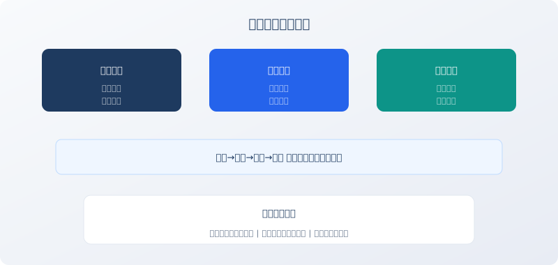
Standard Overview: EN 13001-3-4:2018, "Cranes — General Design — Part 3-4: Limit States and Proof of Competence of Bearings," is the bearing-specific standard within the EU crane design standard EN 13001 series. It defines the limit states for rolling and plain bearings used in cranes (fatigue failure, static strength failure) and specifies the proof-of-competence methodology based on the modified life calculation formula per ISO 281. The standard applies to all crane products within the scope of CE marking.
Every rotating point on a crane—from the hoist drum bearing to the crane bridge wheel bearing—operates under alternating loads. Over a 20-year design life, the bridge wheel bearings of a Class M6 overhead crane can accumulate on the order of 10⁸ revolutions, far exceeding the bearing design basis of typical industrial equipment. EN 13001-3-4 introduces crane-specific load spectrum factors and duty-cycle correction coefficients, moving bearing life calculation from a "general estimation" approach to a "crane-specific precision design" methodology.
Bearing Limit States Defined
EN 13001-3-4 defines two bearing limit states. The fatigue limit state (ULS-F): the appearance of the first fatigue spalling pit on a rolling bearing raceway or rolling element (pitting area ≥1 mm²) marks the end of the bearing's fatigue life. For bearings in critical crane positions (e.g., drum bearing housings), the fatigue failure probability must not exceed 10% (i.e., L₁₀mh modified rating life).
The static strength limit state (ULS-S): under the maximum static load (1.25 times rated load plus the dynamic load factor applied in the static load test condition), the permanent deformation at the contact between the rolling element and raceway must not exceed 1/10,000 of the rolling element diameter. This requirement primarily targets low-speed, heavy-load applications—such as the hook beam bearing of a ladle crane, where rotational speed approaches zero but the load is extreme when carrying a 320 t ladle of molten steel.
Modified Rating Life Calculation (L₁₀mh)
The bearing life formula in EN 13001-3-4 is based on the modified calculation method of ISO 281: L₁₀mh = a₁ × a_ISO × a_crane × L₁₀. Where: a₁ is the reliability correction factor (a₁ = 1 for 90% reliability, a₁ = 0.62 for 95%); a_ISO is the combined lubrication and contamination correction factor recommended by ISO 281 (determined from tables based on the actual lubricant film parameter κ and the cleanliness coefficient ηc); a_crane is the crane-specific duty correction factor unique to EN 13001, assigned by mechanism classification—Class M5 = 1.0, Class M6 = 0.85, Class M7 = 0.7, Class M8 = 0.5. This factor reflects the accelerated bearing fatigue caused by frequent start-stop cycles and impact loads in higher-classified cranes.
As an example, consider the drum bearing (model 22220E) of a Class M5 32 t double-girder bridge crane: basic rating life L₁₀ = 1.2×10⁶ revolutions, a₁ = 1, a_ISO = 1.2 (good lubrication and clean environment), a_crane = 1.0, giving L₁₀mh = 1.44×10⁶ revolutions—equivalent to approximately 25 years of service at 8 hours per day with a 40% duty cycle, meeting the design life requirement.
Crane-Specific Equivalent Dynamic Load Calculation
EN 13001-3-4 specifies calculation rules for the equivalent dynamic load P on crane bearings that differ from general machinery practice. General machinery may use average load, but cranes experience severe load fluctuations (repeated cycles of empty, full, empty), so a load spectrum factor k_P is applied. P = k_P × P_max, where P_max is the equivalent bearing load under maximum working load, and k_P is taken from tables: Class M5 = 0.63, Class M6 = 0.71, Class M7 = 0.80, Class M8 = 0.90. This means that for a Class M5 crane, the equivalent fatigue load over the bearing's life cycle is only 63% of the maximum load—reflecting that no-load and light-load conditions account for most of the operating time.
For bearings subjected to combined radial force Fr and axial force Fa (such as tapered roller bearings and angular contact ball bearings), the equivalent dynamic load P = X×Fr + Y×Fa, where coefficients X and Y are taken from the bearing manufacturer's catalog. However, Fr and Fa must be multiplied by the appropriate dynamic load factor φ according to the crane load combination before substitution into the equation.
Bearing Mounting and Maintenance Requirements
EN 13001-3-4 sets normative requirements for bearing mounting tolerances and lubrication schedules. For cylindrical bore bearings on shafts: Classes M5 through M6 use js6 (transition fit), while Classes M7 through M8 use m6 (light interference fit). The bearing housing bore tolerance is H7. During mounting, bearings must be heated to 80–100°C (oil bath or induction heating); direct flame heating or hammering is strictly prohibited. Heating temperature must not exceed 120°C—above this temperature, bearing steel hardness begins to degrade.
Lubrication schedule: grease-lubricated bearings require regreasing every 2,000 operating hours (Class M5), 1,000 hours (Class M6), and 500 hours (Classes M7 through M8). The amount of fresh grease added should be 30%–50% of the bearing's free internal volume. Oil-bath-lubricated bearings require an oil change every 2,000 hours or 6 months. When changing oil, the bearing housing must be flushed with kerosene before introducing new oil. Mixing greases of different brands or consistencies can cause thickener incompatibility and loss of lubricating function—one of the most common causes of bearing failure in the field.
| Work Duty / Classification | a_crane | load spectrum factork_P | Lubrication Interval(h) | Bearingmatching |
|---|---|---|---|---|
| M5 | 1.0 | 0.63 | 2000 | js6 |
| M6 | 0.85 | 0.71 | 1000 | m6 |
| M7 | 0.7 | 0.80 | 500 | m6 |
FAQ
Q: Why do crane bearings wear out faster than those in general machinery?
A: Three factors are at play: ① Harsh load spectrum — frequent full-load/no-load cycling and start-stop impacts produce an equivalent dynamic load 2–3 times higher than what steady-state equipment like CNC machine tools experience; ② Low speed under heavy load — crane bridge wheel bearings typically run at only 10–50 rpm, making it difficult to establish a full oil film, so a large share of operating time is spent in boundary lubrication; ③ Outdoor contamination — in dusty environments such as cement plants and steel mills, fine particles can migrate past the seal lip and into the bearing even with sealing in place, accelerating abrasive wear. Recommended countermeasures: periodically purge old grease by pumping in fresh grease (a practice known as "wash-out relubrication"), and upgrade the sealing rating to IP66.
Q: What bearing temperature rise is considered normal, and when should we shut down?
A: Under normal operating conditions, the bearing outer ring temperature should not exceed ambient temperature + 40°C — for example, in a 35°C summer environment, the bearing temperature should stay at or below 75°C. When bearing temperature exceeds 85°C, monitoring frequency should be increased and lubrication intervals shortened. If temperature surpasses 95°C, the crane must be stopped immediately to investigate — common culprits include over-greasing (friction from churning), under-greasing (dry running), insufficient bearing clearance (excessive mounting preload), or excessive seal interference. For continuous monitoring, use an infrared thermometer or an online temperature sensor that triggers an automatic alarm and logs trend data when the bearing exceeds the preset threshold.
Q: Why are spherical roller bearings so widely used in crane applications?
A: Spherical roller bearings (e.g., 22200 and 22300 series) account for more than 70% of bearing usage in the crane industry, thanks to three key capabilities: ① Self-aligning — they accommodate 1°–2.5° of angular misalignment between the shaft and bearing housing, compensating for welding distortion in the crane steel structure and installation errors; ② High load capacity — the double-row spherical roller design delivers a dynamic load rating 3–5 times higher than a deep groove ball bearing of the same size; ③ Easy mounting and dismounting — available with adapter sleeves (type H) or withdrawal sleeves (type K) for convenient on-site assembly and disassembly of large bearings. EN 13001-3-4 specifies recommended mounting clearances for spherical roller bearings: C3 clearance for normal-temperature applications and C4 clearance for outdoor gantry cranes subject to wide temperature differentials.
Q: What does abnormal bearing noise sound like, and how do we diagnose it?
A: A healthy rolling bearing produces a steady, low-pitched hum — the continuous sound of rolling elements passing over the raceways. Different fault types produce distinct noise signatures: a rhythmic "clicking" indicates spalling pits on the raceways or rolling elements; a sharp metallic "squeal" points to inadequate lubrication or a damaged cage; an intermittent "clunk" suggests hard foreign particles trapped in the grease. A quick field check can be done with a long screwdriver — place the tip against the bearing housing and the handle to your ear (a simple stethoscope technique) to assess the bearing's running condition. For precise diagnosis, use vibration spectrum analysis: bearing fault characteristic frequencies — f_bpfo (outer ring), f_bpfi (inner ring), f_bsf (rolling element), and f_ftf (cage) — each produce a specific vibration spectrum pattern, and comparing the measured spectrum against these reference frequencies pinpoints the faulty component with confidence.