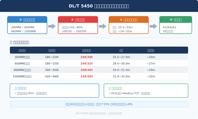
DL/T 5450 Turbine Hall Overhead Crane Selection Guide
DL/T 5450 "Technical Specification for Bridge Crane Selection in Turbine Halls" provides standardized design criteria for the selection parameters, layout arrangements, and civil engineering interface coordination of overhead cranes in the main turbine halls of thermal power plants. It serves as a key reference for power plant design institutes during the process design of main buildings.
Key Selection Parameters and Their Determination
DL/T 5450 defines the core selection parameters for turbine hall bridge cranes: Rated Lifting Capacity, Span, and Lifting Height. The Rated Lifting Capacity should be based on the weight of the generator stator—the heaviest single component in the turbine hall. For ultra-supercritical 1000MW units, the stator weight typically ranges from 420 to 460 metric tons. The standard recommends that when two cranes are used in tandem lifting, each crane's Rated Lifting Capacity should be 55%–60% of the stator weight (accounting for load-sharing imbalance and spreader weight). The crane span should match the main building column spacing. The recommended span is calculated as: (turbine hall span) − (2 × distance from crane runway girder centerline to column face). For typical 300MW units, the span is approximately 26 m; for 600MW units, approximately 29 m; and for 1000MW units, approximately 32 m. After determining the span, the deflection and load-bearing capacity of the crane runway girder must be verified to ensure that the mid-span deflection does not exceed L/800 under full-load conditions.
Layout Arrangement and Interface Coordination
DL/T 5450 requires close coordination with the civil engineering discipline during crane selection. The determination of the crane runway girder rail elevation must consider the following factors: the vertical space occupied by the lifting spreader and hook during stator lifting (typically 3–5 m); the safety clearance from the upper limit switch to the rail top (≥1 m); and the structural height of the trolley frame and hoist. The rail elevation is calculated as: highest lifting point elevation + spreader height + safety clearance + hoist structural height. Based on this, the design institute determines the overall height of the main building and the column cross-section dimensions. The standard also specifies the crane power supply method. For Long Travel (bridge travel), the recommended solution is an Enclosed Conductor Rail system (IP2X Protection Rating), installed on the underside of the walkway plate along the crane runway girder. The Current Collector should be equipped with dual-head brush holders to ensure uninterrupted power supply at expansion joints of the conductor rail. The interface between the crane and the DCS control system adopts a dual-mode approach: Hard Wiring plus Modbus TCP communication. The DCS can remotely monitor the crane's operating status but cannot perform remote control (to prevent misoperation).
Technical and Economic Comparison Method
DL/T 5450 provides a technical and economic evaluation method for crane selection. The evaluation indicators include: equipment purchase cost, installation cost, civil engineering support cost, annual operation and maintenance cost, and lifecycle cost. The standard recommends converting all options into a 20-year lifecycle cost for comparison. Key parameters affecting lifecycle cost include: Work Duty Classification (A3~A5), Variable Frequency Speed Control configuration (with/without), and redundant design level (single-brake vs. Dual Brake). Taking a 600MW unit as an example, the option with A5 (partial VFD speed control + Dual Brake) has an equipment purchase cost approximately 15% higher than the A3 option (Single-Speed + single brake). However, due to improved maintenance efficiency (annual overhaul duration reduced by 2 days) and increased reliability (reduced unplanned downtime), the 20-year lifecycle cost is actually about 8% lower. The standard recommends prioritizing the higher-configuration option when the investment budget permits.
| unit Grade | stator Weight(t) | recommended Lifting Capacity(t) | Span(m) | rail top Elevation(m) |
|---|---|---|---|---|
| 300MWsubcritical | 180~220 | 100/20 | 25.5~27.0 | ~24 |
| 600MWsupercritical | 280~320 | 160/32 | 28.0~30.0 | ~27 |
| 660MWultra-supercritical | 300~350 | 200/40 | 29.0~31.0 | ~29 |
| 1000MWultra-supercritical | 420~460 | 250/50 | 31.0~33.0 | ~32 |
| techno-economic Indicator | A3scheme(foundation) | A4scheme(Standard) | A5scheme(optimization) |
|---|---|---|---|
| equipment procurement cost(10,000 CNY) | ~350 | ~390 | ~410 |
| civil works coordination fee(10,000 CNY) | calculated as incurred | same A3 | same A3 |
| annual maintenance cost(10,000 CNY) | ~15 | ~12 | ~10 |
| Overhaulschedule impact(day/times) | baseline | -1day | -2day |
| 20annual life-cycle cost(10,000 CNY) | ~750 | ~710 | ~690 |
| recommended for adoption | small-capacity unit | conventional600MW | high-utilization unit |
FAQ
Q: Why use a twin-crane tandem lift for turbine hall cranes?
A: The relationship between a single crane's lifting capacity, span, dead weight, and cost is non-linear — once capacity exceeds 250 t, the crane's dead weight rises sharply, and the civil cost of the runway girders and building columns increases substantially. Two 130 t cranes lifting a 260 t stator in tandem cost roughly 25% less in combined equipment and civil works than a single 260 t crane. The two cranes also offer greater flexibility and efficiency for routine light lifts.
Q: Why is runway girder deflection limited to L/800?
A: Excessive girder deflection causes two problems: uneven travel resistance for the crane bridge, which can lead to unintended creeping in severe cases, and elastic deformation that creates step offsets at rail joints, accelerating wheel and rail wear. L/800 is an engineering benchmark derived from bridge travel smoothness and rail joint service life. For cranes with travel speeds of 40 m/min or higher, L/1000 is recommended.
Q: What is the difference between DL/T 5450 and DL/T 1419 in crane selection?
A: DL/T 1419 focuses on the crane's own technical parameters — lifting speed, work duty, mechanism configuration, etc. — and serves as the selection basis for crane design and manufacturing. DL/T 5450 addresses the coordination between the crane and the main building design — span, rail elevation, and civil interfaces — and serves as the selection guide for power plant design institutes. The two standards complement each other and together form a complete technical framework for power plant crane selection.
Q: Is DCS connectivity mandatory for the crane?
A: DL/T 5450 recommends DCS connectivity but does not make it a mandatory requirement. The benefit is that operators can monitor crane status — position, load, and fault alarms — from the control room. However, the standard explicitly prohibits remote crane operation via DCS; all crane movements must be performed from local controls. This is a safety measure: DCS operators cannot observe the actual lifting site. The primary value of DCS connectivity lies in long-term status logging and trend analysis.