

Online Inspection System for Overhang Wear on Overhead Crane Wheels and Analysis System for Wheel-Rail Interaction
📋 The online wheel flange wear detection system for overhead cranes uses a 2D laser profile sensor to scan the wheel tread and flange profiles, with a flange thickness measurement accuracy of ±0.1 mm. It combines this data with the Hertzian wheel-rail contact model to predict the remaining service life of the wheel.
Flange wear and tread wear on the wheels of overhead cranes are the primary causes of rail gouging, abnormal operating noises, and premature wheel failure. References for wheel design and service life assessment:GB/T 3811-2008 "Code for the Design of Cranes"According to the GB/T 4621-2006 standard for flange thickness measurement, traditional methods involve manually measuring flange thickness and tread diameter using a vernier caliper, which requires stopping the crane and moving the rail car—a labor-intensive process with a limited number of measurement points (typically only 2 to 4 points per rail). The KL-WHEEL-LASER system installs a 2D laser profile sensor at the track end. As the crane passes by, it automatically scans the full profile of the tread and flange of each set of wheels, with a single data acquisition taking only 0.2 seconds, with a flange thickness measurement accuracy of ±0.1 mm and a tread diameter accuracy of ±0.3 mm.
Principles of Laser Profile Measurement
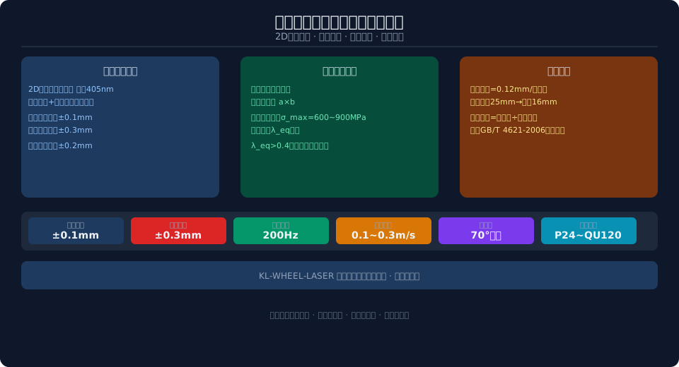
Krud Heavy Industry Systems installed two 2D laser profile sensors (Keyence LJ-X8060, blue laser 405 nm, Z-axis repeatability of 0.4 μm) at the track end, aligned respectively with the contact patch between the wheel tread and the rail and the outer edge of the wheel flange. When the train passes through the inspection area at a low speed of 0.1–0.3 m/s, each sensor acquires cross-sectional data of the wheel profile at a frequency of 200 Hz. Encoder-triggered equidistant sampling ensures that each wheel yields ≥50 cross-sectional profile data points. The system extracts key parameters from the contour point cloud: flange thickness (measured at a height of 12 mm from the tread reference line, in accordance with the GB/T 4621-2006 standard), tread diameter (least-squares circular fit), tread wear depth (compared to the original reference profile), and flange angle (standard 70°).
Inspection data is automatically compared with historical records to generate trend curves. When the flange thickness wear exceeds 30% of the initial thickness, the tread diameter decreases by more than 5 mm, or the flange angleAn alert is triggered when the angle is less than 65°. The system operates fully automatically without human intervention, completing a full inspection cycle with each pass. It can identify parameters for more than 8 different wheel models and automatically adjust the inspection thresholds accordingly.
Wheel-Rail Interaction Analysis and Service Life Prediction
The contact behavior between the wheel and the rail is modeled using Hertzian contact theory: the contact patch is elliptical, with the semi-major axis a and semi-minor axis b determined by the wheel curvature radius R_w, the rail curvature radius R_r, the wheel load P, and the material elastic modulus E. The maximum contact stress at the contact patch is σ_max = 3P/(2πab). For the ZG340-640 wheels and QU80 rails commonly used in overhead cranes, σ_max is approximately 600–900 MPa under full load. When the flange thickness is worn down toWhen the contact spot is less than 20 mm, it shifts toward the root of the flange, causing the stress concentration factor at the flange root to increase by 1.5 to 2 times, which accelerates the initiation of fatigue cracks at the flange root.
The KL-WHEEL-LASER system automatically calculates the wheel-rail contact angle λ and the equivalent taper λ_eq based on the measured values of flange thickness and tread diameter. When λ_eq > 0.4, the system indicates a poor wheel-rail match and recommends wheel turning or replacement. The system also uses data from five inspections to predict the wheel’s remaining service life: flange thickness wear rate (mm/10,000 km) × current remaining thickness = remaining operating distance (10,000 km). Taking a 32-metric-ton overhead crane at a certain steel mill as an example, the wheel flange wear rate is approximately 0.12 mm/10,000 km (based on an average daily operation of 12 hours). When the flange thickness wears down from the initial 25 mm to the warning value of 16 mm, the remaining service life is approximately 750,000 km (about 14 months).
Applications and Installation Solutions
The KL-WHEEL-LASER system is suitable for online inspection of various types of overhead crane wheels, covering bridge cranes (track spans of 10–40 m), gantry cranes (track spans of 18–60 m), and suspended cranes (I-beam tracks). The laser profile sensor is installed at the rail end and secured to concrete foundations on both sides of the rail using custom brackets. The brackets are made of 304 stainless steel (8 mm thick) and are height-adjustable within a range of ±50 mm to accommodate rail height variations. The sensors have an IP67 protection rating and can operate continuously in temperatures ranging from −20 to +60°C and at a relative humidity of 95%. The sensors are connected to an edge gateway via industrial Ethernet (Cat6a, transmission distance ≤ 100 m), and the gateway is housed in a nearby electrical enclosure (IP54 protection rating).
In scenarios where multiple overhead cranes share the same track (such as multiple cranes within the same bay at a steel mill), the system supports multi-crane identification: by installing RFID tags (operating frequency 902–928 MHz UHF, read range 0–5 m) on each crane, and by installing RFID readers at the track terminals, the system automatically identifies the crane number as the crane passes through the detection zone and records the data in the corresponding equipment file. After implementing this solution for 42-metric-ton overhead cranes (six units operating in the same bay) at a certain steel mill, the system automatically collects profile data for all 48 sets of wheels across all six cranes each month, replacing the manual inspection process that previously required two days per month. Within six months of the system’s commissioning, it issued early warnings for three instances of flange wear exceeding limits; in all cases, wheel turning was completed within the scheduled maintenance window, preventing wheel scrapping and further track gouging. The Krude Heavy Industry Wheel Inspection System has been deployed and is operational at more than 20 steel and port enterprises.
| Installation Environment | Sensor Configuration | Installation Location | Test Accuracy | Applicable Scenarios |
|---|---|---|---|---|
| Indoor Factory Building | LJ-X8060 Blu-ray Standard | Side view of the track terminal | ±0.1 mm | Overhead Cranes/Gantry Cranes/Suspended Cranes |
| Open-air storage yard | LJ-X8060+ Lens Hood | Installation Inside the Protective Enclosure | ±0.15 mm | Port Gantry Cranes |
| High-Temperature Workshop | LJ-X8060+ Water-Cooling Sleeve | Water-Cooled Base Installation | ±0.15 mm | Metallurgy/Foundry Cranes |
Comparison of Detection Technologies
| Dimensions of Comparison | Manual Caliper Inspection | Laser Profile Inspection |
|---|---|---|
| Rim Thickness Tolerance | ±0.5 mm | ±0.1 mm |
| Testing Time | 30 min per unit (setup required) | 0.2 seconds per unit (test performed upon passage) |
| Coverage Rate | 2–4 points per round | Full-Contour Continuous Scan |
| Data Traceability | Paper Records | Electronic Trend Curve |
| Tire Life Prediction | 无 | Based on a wear rate model |
| Wheel-Rail Matching Analysis | 无 | Automatically Calculate Equivalent Taper |
Frequently Asked Questions
Q: Is the accuracy of laser detection affected by strong outdoor light?
Answer: Using a blue laser (405 nm) combined with a narrowband filter (center wavelength 405 nm, bandwidth 10 nm), the system maintains an accuracy of within ±0.15 mm even under ambient light conditions of 10,000 lux. The system is also equipped with a light shield to protect against direct sunlight.
Q: Can the system simultaneously detect diagonal errors caused by wheel diameter deviations?
Answer: Yes. The system simultaneously records the diameter, flange thickness, and tread profile of all four wheels and automatically calculates the diagonal wheel diameter difference. GB/T 10183-2020 specifies that the diagonal difference must be ≤1 mm; if the difference exceeds this limit, the system immediately issues an adjustment recommendation.
Q: Are there strict speed control requirements for overhead cranes when passing through the inspection area?
Answer: A speed of 0.1–0.3 m/s is recommended to ensure a contour data density of ≥50 cross-sections per wheel. Excessively high speeds will result in sparse profile data; however, the system can still operate normally at speeds up to 0.5 m/s (≥30 cross-sections per wheel), though the flange thickness accuracy will decrease to ±0.2 mm.
Q: Does Krude Heavy Industry’s solution support simultaneous inspection of both single-track and double-track systems?
Answer: Yes. The system deploys one laser sensor array on each rail of a dual-rail track, automatically collecting data from the wheels on both sides in sync as the crane passes by. In single-rail scenarios (such as overhead cranes), a sensor on only one side may be deployed; the mounting bracket accommodates rail base widths ranging from 50 to 220 mm.
