

Bridge Crane Installation & Commissioning: Rail to Load Test
Installing an overhead crane might look like a simple sequence—lay the rails, lift the girders into place, and wire it up—but in practice, every step demands precision. A 2 mm deviation in the rail can cause the crane bridge to experience rail gnawing (wheel flange rubbing). A single-phase sequence error in the electrical wiring will make the motors run in reverse. And without a properly executed load test, the installation won't pass the completion acceptance. We've seen many factories attempt DIY installations to save costs, only to face recurring issues shortly after, eventually having to hire a professional crew to redo the work.
This guide breaks down the entire overhead crane installation process, from pre-installation preparation to completion acceptance—covering rail alignment, girder hoisting, electrical adjustments, and testing procedures, step by step.
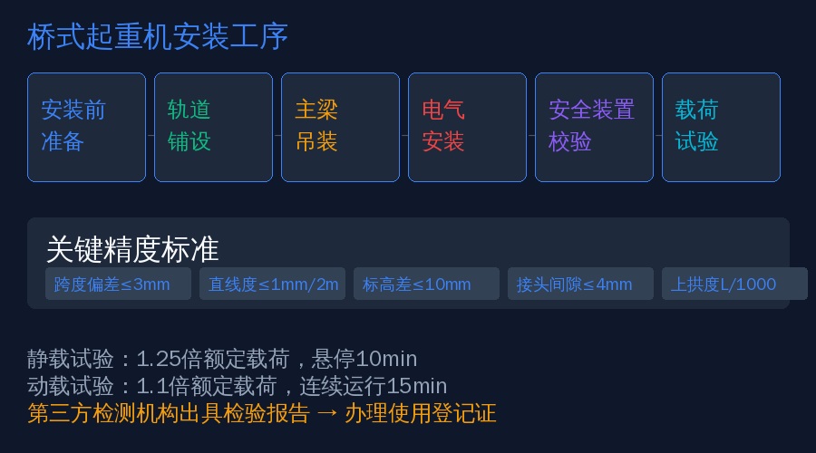
Pre-Installation Preparation
1.1 Reviewing Drawings and Documentation
Before installation begins, the following technical documents must be obtained: the crane general arrangement drawing and component drawings, rail installation drawing, electrical schematic and wiring diagram, foundation anchor bolt layout, product certificate, and factory acceptance test report. Verify that key parameters—span, lifting height, work duty classification, and rail type—match the on-site conditions.
1.2 Verifying Site Readiness
- Concrete strength of the factory building corbels (runway beams) must reach 100% or more of the design value.
- Anchor bolt embedment position deviation must be ≤5 mm, and elevation deviation within ±10 mm.
- The installation site must have adequate hoisting space and lifting equipment (truck crane or truck-mounted crane, with tonnage selected based on the main girder weight).
- Construction power supply must be connected, with the voltage grade matching the equipment requirements.
- Safety measures in place: a warning zone set up below the work area with caution tape, warning signs posted, and a designated safety monitor on duty.
1.3 Installation Tools and Equipment
The table below lists the essential instruments and tools required for the installation team:
| Tool/Instrument | Application | accuracy requirements |
|---|---|---|
| Level Instrument | Rail Elevation Measurement | ±0.5mm/km |
| theodoliteortotal station | rail straightness/Span Measurement | ±1" |
| steel coil Ruler(viaverification) | Span Measurement | ±1mm/50m |
| Megohmmeter (Insulation Tester)(500V) | Insulation Resistance Test | — |
| multimeter/clamp meter | Electrical Commissioning | — |
| torque wrench | High-Strength Bolt Tightening | ±4% |
| Test Weight(or substitute) | Load test | ±1%rated load |
Rail Installation and Alignment
The crane rail is the "runway" for the overhead crane—if it isn't installed properly, the crane simply won't perform as it should. Rail installation is the single most critical step in the entire crane erection process.
2.1 Rail Laying
Rails are typically QU70 or QU80 crane-specific steel rails, secured to the runway beam with clamp plates. Laying requirements:
- Rail joint gap ≤ 4 mm, joint height difference ≤ 1 mm, and lateral offset ≤ 1 mm (ISO 12478)
- Span deviation: ≤ 3 mm for spans up to 19.5 m; ≤ 5 mm for spans exceeding 19.5 m
- Rail straightness: ≤ 1 mm over any 2 m length, ≤ 5 mm over the full length
- Elevation difference between the two rails at the same cross-section: ≤ 10 mm referenced to the columns, ≤ 15 mm over the full length
- Rail earthing resistance ≤ 4 Ω
2.2 Rail Alignment Procedure
Begin with rough laying, then use a theodolite to align each section progressively, tightening the clamp plates as you go. The alignment sequence is: level first, then straightness, and finally span verification. Span measurement is performed with a calibrated steel tape measure and a spring tension meter (tension 150 N), with temperature correction applied. Measurements taken at −10 °C in winter can differ from those at 35 °C in summer by 2–3 mm.
Main Girder and End Carriage Erection
3.1 Lifting Plan
For small- and medium-capacity overhead cranes (≤ 50 t), the split-erection method is commonly used—each main girder is lifted and positioned individually before the end carriages are connected. For large-capacity cranes (> 50 t), integral lifting or a specialized spreader is recommended. Before lifting, calculate the lifting point locations (the center of gravity of the main girder is typically offset 5–8% from the span center toward the drive side), and the lifting lug welds must undergo flaw detection.
3.2 Assembly and Connection
- Connection bolts between the main girder and end carriage must be tightened in stages to the design torque (initial tightening at 50%, then final tightening to 100%). For bolts M24 and above, a hydraulic torque wrench or torque multiplier is recommended.
- After connection, measure the camber of the main girder: the camber at mid-span should be between 0.9/1000 and 1.4/1000 of the span (FEM 1.001). Insufficient camber indicates inadequate structural stiffness, while exceeding the upper limit suggests excessive pre-camber.
- Welding of the trolley rail to the main girder flange plate must be performed in accordance with the Welding Procedure Specification (WPS), followed by Ultrasonic Testing (UT) of the welds.
Electrical System Installation and Commissioning
4.1 Power Supply and Wiring
The crane can be powered either via conductor rails (enclosed conductor rail or angle-steel conductor rail) or a cable reel. Conductor rail installation requires parallelism of ± 5 mm over the full length, with uniform contact pressure between the current collectors and the conductor rail. For the main circuit, verify the phase sequence and confirm correct motor rotation direction.
4.2 Electrical Commissioning Procedure
- Insulation test: main circuit-to-ground insulation resistance ≥ 1 MΩ (500 V megohmmeter); control circuit ≥ 0.5 MΩ
- No-load test run: operate each mechanism individually without load to check direction, speed, limit switch operation, and brake clearance
- Combined test run: operate the crane bridge, trolley, and hoisting mechanism together to verify coordination and interlock functions
- Protective function testing: test the overload limiter, travel limit switches, hoisting height limiter, emergency stop button, zero position protection, and undervoltage protection one by one. Each must operate reliably.
- Continuous operation test: run each mechanism at rated speed for 1 hour (hoisting mechanism with 50% rated load), monitoring motor temperature rise (≤ 80 K) and brake temperature (≤ 120 °C)
Safety Device Verification
The following safety devices must be verified individually with recorded data:
| safety device | verification Content | acceptance criteria |
|---|---|---|
| Overload Limiter | 105%rated load Alarm when,110%Power off when | operating error≤±5% |
| Hoisting Height Limiter | Hook Raise to upperlimit switchwhenautomatic shutdown Hoisting / Lifting Circuit | Hookand Drummaintain between≥2turns Wire Rope |
| Travel Limit Switch | Crane Bridge/Cross Travel / Trolley Travelbefore terminalautomatic decelerationand stop | at Bufferstop before |
| Emergency Stop Button | after pressing, allmechanismimmediate stop | after reset, eachmechanismcannot self-start |
| Zero Position Protection | Controllercannot start when not at zero position | reliable operation |
| Wind Protection Device / Rail Clamp | Rail clamp/Anchor devicefunctional test | Brakingforce≥design value |
6. Load Testing
The load test is the final checkpoint in installation acceptance and the most direct way to verify overall crane performance. Testing is carried out in accordance with FEM 1.001 Crane Test Specification and consists of three stages:
6.1 Rated Load Test (100% SWL)
Hoist the rated load and perform three complete cycles of hoisting, lowering, long travel (bridge travel), and cross travel (trolley travel). All mechanisms must operate smoothly with reliable braking and no abnormal noise or vibration. Throughout the full cycle — from floor level to maximum hook height and back down — the camber of the main girder must not change by more than 1/1000 of the span.
6.2 Static Load Test
Hoist 1.25 times the rated load, raise it approximately 100 mm off the ground, and hold for 10 minutes. After removing the load, inspect the main girder for permanent deformation — the residual camber must not be less than 0.7/1000 of the span. Check that the main girder weld seams, end carriage connections, and trolley frame show no cracks or visible deformation.
6.3 Dynamic Load Test
Hoist 1.1 times the rated load and operate all mechanisms simultaneously within safe speed limits to simulate real lifting and transport conditions. Run continuously for at least 15 minutes. All mechanisms must show no abnormal temperature rise, shock, or vibration, and braking must be smooth. Measure the steady-state current of each motor — readings must remain within the rated range.

Final Thoughts
Installing an overhead crane is not a "bolt it on and it's good to go" job. A slight deviation in track accuracy, an undertorqued bolt, or a safety device that's not properly adjusted — these issues may go unnoticed during routine operation, but they can turn into serious incidents when you least expect them. Following the acceptance procedure strictly is not just about protecting the equipment — it's about protecting people. Whether you're preparing to install a new overhead crane or planning an overhaul and reinstallation of an aging unit, this guide gives you a practical, step-by-step reference to work from.
FAQ
Q: How long does a typical bridge crane installation take?
A: For small to medium overhead cranes up to 30 t, a qualified installation crew typically completes the entire process — from pre-installation preparation to completion acceptance — in 7 to 15 working days. This includes 2–3 days for rail installation, 2 days for main girder lifting and assembly, 3–4 days for electrical installation and commissioning, and 1–2 days for load testing and safety device verification. Projects involving large tonnage (over 100 t) or long spans (over 30 m) will require proportionally more time.
Q: Is load testing mandatory after installation, and who should perform it?
A: Yes, it is mandatory. Both ISO 4301 Crane Design Standard and TSG 51-2023 Crane Safety Technical Supervision Regulation explicitly require load testing after installation. Both the static load test (1.25 times rated load) and the dynamic load test (1.1 times rated load) are non-negotiable. We recommend having a qualified third-party inspection institution perform the tests and issue a formal inspection report — this report is a required document for obtaining the use registration certificate.
Q: Can we reuse the existing crane rails when replacing an overhead crane in a renovated old workshop?
A: It's possible, but only after the existing rails have been thoroughly re-inspected: measure span, elevation difference, straightness, wear amount (rail head width wear must not exceed 5 mm), and check the condition of clamping plates and bolts. In many cases, old rails have already exceeded acceptable wear and deformation limits, and reusing them will compromise the operating accuracy and service life of the new crane. We recommend having a professional team assess the rails before making a decision — saving money on new rails now may cost you far more in frequent rail gnawing (wheel flange rubbing) and maintenance headaches later.
