

Crane Rail Installation, Alignment & Maintenance
Crane Rail Installation and Maintenance: Rail Selection, Alignment Accuracy, and Troubleshooting
Crane rails are the foundation of safe and reliable crane operation. The quality of rail installation directly affects the crane's running performance, wheel wear, and overall service life. This guide covers rail profile selection, installation tolerances, inspection methods, joint treatment, and common fault diagnosis — with practical solutions you can apply on site.
How to Select the Right Crane Rail Profile
Choosing the correct rail profile is the first step in any crane runway project. The rail must match the crane's wheel load, duty class, and operating environment. Common rail profiles include square rails (e.g., P38, P43, P50, QU70, QU80, QU100, QU120) and flat-bottom rails. For heavy-duty cranes with high wheel loads, QU-series rails are typically preferred due to their higher section modulus and better wear resistance. For lighter or medium-duty applications, P-series rails offer a cost-effective solution without compromising performance.
When selecting a rail profile, consider the following factors:
- Wheel load and contact stress: The rail head width must be sufficient to distribute the wheel load without excessive contact stress, which can cause premature rail head wear or plastic deformation.
- Duty class: Cranes with higher duty classifications (e.g., A6–A8 per ISO 4301) require rails with greater hardness and section strength to withstand frequent starts, stops, and heavy loads.
- Operating environment: For outdoor or corrosive environments, consider rails with enhanced surface treatment or corrosion-resistant materials.
- Runway length and thermal expansion: Longer runways require rails with proper expansion joint provisions to accommodate thermal movement.
Rail Installation Tolerances and Alignment Requirements
Precise alignment is critical for smooth crane travel and even load distribution across the wheels. The following tolerances are widely accepted in the industry and align with ISO 4301 and ISO 12480 guidelines:
| Parameter | Tolerance |
|---|---|
| Rail gauge (span) deviation | ±5 mm for spans up to 16.5 m; ±8 mm for spans above 16.5 m |
| Rail elevation (height) deviation | ±5 mm along the runway; adjacent supports within ±2 mm |
| Rail straightness (horizontal) | ≤2 mm over any 2 m length |
| Rail straightness (vertical) | ≤2 mm over any 2 m length |
| Rail top surface slope | ≤1:1000 along the runway direction |
These tolerances ensure that the crane wheels maintain proper contact with the rail head, minimizing lateral forces that lead to rail gnawing and uneven wheel wear. Use a precision level, theodolite, or laser alignment system to verify these parameters during installation and periodic inspections.
Rail Joint Treatment and Welding Best Practices
Rail joints are the most vulnerable points on a crane runway. Poorly executed joints cause impact loads, noise, and accelerated wear on both the rail and the crane wheels. Two common joint types are used: fishplate (bolted) joints and welded joints.
Fishplate joints are easier to install and allow for thermal expansion, but they require regular bolt torque checks and periodic alignment verification. The rail ends must be cut square and the fishplate bolts tightened to the specified torque. A gap of 2–4 mm should be left between rail ends to accommodate thermal expansion.
Welded joints provide a continuous running surface, eliminating impact at the joint. When welding rails, use the appropriate welding consumables and preheat the rail ends to the recommended temperature. After welding, grind the weld flush with the rail head and check the surface hardness — it should match the parent rail material to avoid premature wear. Post-weld inspection with ultrasonic testing is recommended for critical runways.
Regardless of joint type, the vertical and horizontal offset at the joint must not exceed 1 mm. Any step or misalignment will cause dynamic impact loads that propagate through the crane structure.
Common Crane Rail Faults and Troubleshooting
Even with proper installation, crane rails can develop faults over time. The most common issue is rail gnawing (also called rail biting or wheel flange wear), where the wheel flange contacts the rail side, causing characteristic wear patterns and abnormal noise. Rail gnawing is typically caused by one or more of the following:
- Rail gauge deviation: If the rail span is too narrow or too wide, the wheels will constantly contact one side of the rail head.
- Rail misalignment: Horizontal or vertical misalignment causes the crane to crab, forcing the flanges against the rail sides.
- Wheel misalignment: Worn bearings, bent axles, or improper wheel tread profiles can cause the crane to travel at an angle to the rail.
- Uneven wheel loading: Differences in wheel diameters or spring compression cause the crane to tilt, increasing flange contact on one side.
- Runway deformation: Foundation settlement or structural deflection can change the rail geometry over time.
To diagnose rail gnawing, start by measuring the rail gauge at multiple points along the runway and comparing the readings to the design values. Next, check the rail straightness and elevation using a laser alignment system. Inspect the wheel flanges for wear patterns — a bright, polished area on one side of the flange indicates continuous contact. Also, measure the wheel diameters and check for out-of-round conditions.
Once the root cause is identified, corrective actions may include:
- Realigning the rails to within tolerance using shims and rail clamps.
- Adjusting the wheel positions or replacing worn wheels and bearings.
- Grinding the rail head to restore the correct profile and remove any raised metal at joints.
- Re-torquing fishplate bolts and replacing worn fishplates.
- For severe cases, replacing the affected rail section.
Rail Inspection and Preventive Maintenance Schedule
Regular inspection is the most cost-effective way to extend crane rail life and prevent unplanned downtime. A typical inspection program includes the following checks:
| Inspection Item | Frequency | Acceptance Criteria |
|---|---|---|
| Rail gauge and alignment | Annually | Within tolerances listed above |
| Rail head wear | Every 6 months | Vertical wear ≤ 3 mm; side wear ≤ 2 mm |
| Rail joint condition | Every 3 months | No visible step; bolts torqued to spec |
| Rail fasteners and clamps | Every 6 months | No loose or missing fasteners |
| Rail surface condition | Every 3 months | No spalling, cracks, or corrosion pitting |
In addition to scheduled inspections, perform a visual check of the rail runway whenever the crane exhibits unusual noise, vibration, or travel behavior. Early detection of minor issues prevents them from escalating into costly repairs or safety hazards.
Frequently Asked Questions
Q: What is the maximum allowable rail wear before replacement is required?
A: The maximum allowable vertical wear on the rail head is typically 3 mm for QU-series rails and 2 mm for P-series rails. Side wear on the rail head should not exceed 2 mm. If wear exceeds these values, the rail should be replaced or re-profiled to prevent wheel flange damage and potential derailment.
Q: How often should crane rail alignment be checked?
A: A full alignment survey should be performed at least once a year, or more frequently for cranes operating under heavy duty cycles or in harsh environments. Additionally, alignment should be checked after any foundation work, rail replacement, or significant crane modification.
Q: Can rail gnawing be repaired without replacing the rail?
A: In many cases, yes. If the gnawing is caused by misalignment, realigning the rails and correcting the wheel geometry will stop further wear. The worn rail side can be ground smooth to remove any sharp edges. However, if the rail head has lost significant section due to wear, replacement is the safer option.
Q: What is the recommended gap for fishplate rail joints?
A: A gap of 2–4 mm is recommended for fishplate joints to accommodate thermal expansion. The gap should be measured at the ambient temperature during installation. For welded joints, no gap is left, but the weld must be ground flush and inspected for defects.
A: The crane rail is the "runway" for an overhead crane, and its condition directly impacts the crane's operating stability and safety. Common issues with crane rails include rail gnawing (wheel flange rubbing), uneven rail joints, rail wear, and rail settlement.
Rail Selection: Common rail models include QU70 (43kg/m), QU80 (50kg/m), QU100 (63kg/m), and QU120 (80kg/m). Selection is determined by the crane's Maximum Wheel Load—QU80 is recommended for 30-ton Bridge Cranes, while QU100 is suitable for 50 to 100-ton cranes.
Installation Accuracy: The allowable height difference on the rail top surface is ≤10mm (within the same cross-section), the rail centerline deviation must be ≤5mm, the rail joint gap should be 1–2mm, and the joint height difference must be ≤1mm. After installation, precision Level Instruments and theodolites are required for verification.
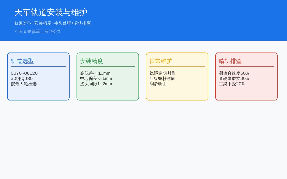
Addressing Rail Gnawing: The three most common causes of crane rail gnawing are installation deviation (accounting for 50% of cases), Wheel Flange wear (30%), and Main Girder deformation (20%). The recommended troubleshooting sequence is: first measure rail straightness, then inspect Wheel Flange wear, and finally check for main girder deflection.
Rail Types and Selection Criteria
Crane rails are manufactured to the ISO 4301 standard. Common models include QU70 (43kg/m), QU80 (50kg/m), QU100 (63kg/m), and QU120 (80kg/m). The number in the model designation indicates the width of the rail head in millimeters. Rail selection is based on the crane's Maximum Wheel Load—the relationship between wheel load and rail head width is as follows: QU70 is applicable to wheel loads up to 250kN (for cranes up to approximately 25 tons), QU80 for loads up to 350kN (for cranes in the 30 to 50-ton range), QU100 for loads up to 500kN (for cranes between 50 and 100 tons), and QU120 for loads exceeding 500kN (for cranes over 100 tons). Rail steel is typically U71Mn or U75V, with a hardness of HB260–300, offering excellent Wear Resistance and resistance to crushing.
Track Gauge is a core indicator for rail maintenance. When the gauge deviation of a crane rail exceeds the allowable range, it leads to increased friction between the Wheel Flange and the rail side—this is the most common cause of rail gnawing. The measurement method for Track Gauge involves using a dedicated gauge ruler at the mid-span position, taking 3 to 5 measurement points per rail (at both ends and the middle) and calculating the average. Measurement records should be kept for trend analysis—if the gauge deviation increases month over month, it indicates potential overall rail displacement, requiring inspection of the Rail Clamp and rail foundation.
Routine Maintenance Points for Crane Rails
Routine maintenance for crane rails includes: weekly inspection of Rail Clamps and bolts for loosening—vibration during crane operation gradually loosens clamp bolts, and loose clamps can lead to rail displacement. Monthly measurement of Track Gauge and rail straightness—use a steel tape to measure the mid-span gauge (tolerance ±5mm) and the string line method to check rail straightness (tolerance ±2mm per 10m). Quarterly inspection of rail joints—check for misalignment and excessive joint gap. Annually, conduct a thorough examination of the rails in conjunction with the crane's Annual Inspection—this includes checking rail wear depth (replacement is required if it exceeds 4mm), rail settlement (foundation adjustment is needed if it exceeds 10mm), and overall changes in rail Elevation.
FAQ
Q: Which rail type should be used for an overhead crane?
A: Common models include QU70, QU80, QU100, and QU120. QU80 is recommended for 30-ton Bridge Cranes, while QU100 is suitable for 50 to 100-ton cranes. Selection is based on the crane's Maximum Wheel Load.
Q: Where should I start troubleshooting rail gnawing?
A: Follow this sequence: first measure rail straightness, then inspect Wheel Flange wear, and finally check for main girder deflection. Installation deviation accounts for 50% of rail gnawing causes, Wheel Flange wear for 30%, and Main Girder deformation for 20%.
