Crane Wheel Technical Guide: Selection, Heat Treatment & Maintenance

Complete crane wheel technical manual covering six core modules: material selection, heat treatment process, installation tolerances, routine maintenance, wear assessment, and replacement criteria. Each module has its own in-depth article; this page serves as the series overview and quick-reference hub.

Crane bridge wheels are critical components that bear the total machine weight and transmit the driving force for bridge travel. Every stage of their lifecycle—selection, heat treatment, installation, maintenance, wear assessment, and replacement—is interconnected. This wheel-focused series from Kelude systematically covers the full lifecycle technology across six chapters. Below is a quick-reference summary of the key points and critical parameters from each section.

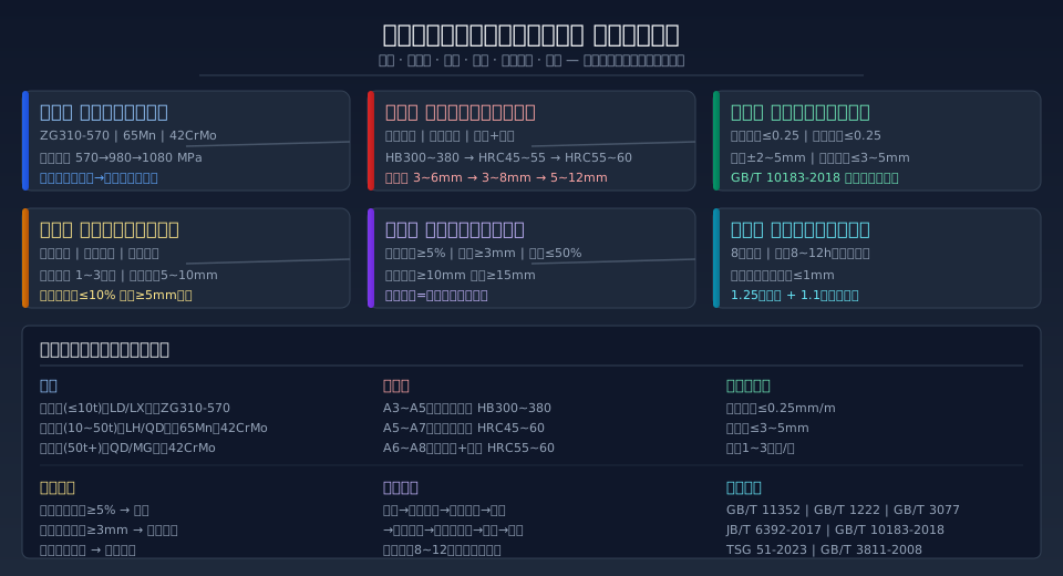
Crane wheel lifecycle technical manual overview of six chapters: selection, heat treatment, installation, maintenance, wear, replacement


Chapter 1: Wheel Material Selection & Load Capacity

The three primary materials for crane wheels are ZG310-570 cast steel, 65Mn spring steel, and 42CrMo alloy structural steel. ZG310-570 offers a tensile strength of ≥570 MPa and suits small-to-medium cranes in the 5–50 t range. 65Mn provides ≥980 MPa tensile strength for medium-duty cranes from 10–100 t. 42CrMo, with a tensile strength of ≥1080 MPa, is the preferred choice for large-tonnage cranes above 50 t. Refer to the dedicated chapter article for detailed comparison tables covering chemical composition, mechanical properties, heat treatment parameters, and load capacities for each material.

For light-duty, low-frequency applications (A3–A5 duty classes), the ZG310-570 flame-hardening option delivers the best cost efficiency, with wheel costs running approximately 50%–60% of a 42CrMo solution. However, if the equipment is planned for a service life exceeding 10 years or annual operation beyond 3,000 hours, the 42CrMo induction-hardening option is the better choice, offering superior life cycle cost.

For detailed parameter comparisons and recommended configurations by tonnage, see Chapter 1.


Chapter 2: Heat Treatment & Hardness Standards

Flame surface hardening, induction hardening, and quenching-and-tempering combined with induction hardening are the three mainstream heat treatment processes for crane wheels. Flame hardening requires simple equipment and offers the lowest cost, achieving a hardened layer depth of 3–6 mm—suitable for ZG310-570. Induction hardening provides fast heating, minimal deformation, and uniform hardness, with a hardened layer depth of 3–8 mm, ideal for 65Mn and 42CrMo. Quenching-and-tempering plus induction hardening delivers the best overall performance, reaching a hardened layer depth of 5–12 mm for large-tonnage 42CrMo wheels.

Post-hardening tread hardness ranges are as follows: ZG310-570 flame-hardened wheels achieve HB300–380; 65Mn induction-hardened wheels reach HRC45–55; and 42CrMo quench-and-tempered plus induction-hardened wheels attain HRC55–60. At acceptance, the hardness variation across four points on the same wheel must not exceed HB30 for flame-hardened wheels or HRC5 for induction-hardened wheels.

For process parameters, hardness ranges, inspection methods, and process comparison tables, see Chapter 2.


Chapter 3: Installation Tolerances & Rail Fit

Wheel installation accuracy directly determines the smoothness of bridge travel and the likelihood of rail gnawing. Per ISO 12488 (replacing GB/T 10183-2018), horizontal skew must not exceed 0.25 mm/m for wheels with a diameter greater than 500 mm, and vertical skew is limited to 0.25 mm/m with an absolute maximum of 0.5 mm. Wheel base tolerance checks: ±2 mm when S ≤ 10 m; ±[2 + (S − 10) × 0.1] mm when S > 10 m. The diagonal difference must be ≤3 mm for trolley wheel bases and ≤5 mm for bridge wheel bases.

Adjustment methods include using eccentric bushings to correct horizontal skew, shims for vertical skew, and prioritizing adjustments on the driven wheel side to rectify diagonal differences. For multi-wheel configurations (8-wheel or 16-wheel), a spreader beam is required to ensure uniform contact between all wheels and the rail.

For all tolerance specifications, inspection tools, adjustment procedures, and multi-wheel load-equalization solutions, see Chapter 3.


Chapter 4: Routine Maintenance & Inspection Intervals

Wheel maintenance centers on four core tasks: bearing lubrication, tread surface inspection, wheel flange measurement, and bridge travel deviation detection. Bearing lubrication is required every 3 months for A3–A5 duty classes, and monthly for A6–A8 classes. Use grease grades 2–3 for normal operating conditions, and a composite lithium-based grease for high-temperature service.

The tread surface should be visually inspected monthly for cracks and spalling, while wheel flange thickness is measured quarterly. The flange-to-rail clearance standard is 5–10 mm; adjustment is required if the clearance exceeds 15 mm or falls below 3 mm. Bridge drive motor current should be checked every six months—a difference exceeding 10% between the two sides indicates travel deviation.

For the maintenance interval comparison table, grease selection guidance, and bearing abnormal noise diagnosis methods, see Chapter 4.


Chapter 5: Wheel Wear Assessment & Discard Criteria

Scrapping thresholds for the four primary crane wheel failure modes: uniform tread wear with diameter reduction ≥5%; tread spalling with a single pit ≥200 mm² or depth ≥3 mm; wheel flange thickness ≤50% of original thickness; any crack at the flange root requires immediate scrapping; transverse tread cracks ≥10 mm or longitudinal cracks ≥15 mm.

Inspection methods include using a vernier caliper to measure the wheel flange, a wheel diameter gauge for the tread surface, a 10× magnifying glass to detect cracks, and Magnetic Particle Inspection (MPI) for confirmation. If the diameter difference among the four wheels on the same end carriage reaches ≥1.5 mm, the wheels must be replaced as a matched set.

For detailed acceptance criteria, inspection methods, and a comparison table for each failure mode, see Chapter 5


Chapter 6: Wheel Replacement Criteria and Operating Regulations

The eight-step wheel replacement procedure: remove the old wheel (1 hr) → inspect and repair the end carriage (2 hrs) → heat-fit the bearing (0.5 hr) → press-fit the wheel (1 hr) → adjust skew (2 hrs) → adjust wheel base and diagonal dimensions (1 hr) → No-Load Test Run (2 hrs) → load test (3 hrs). Total time for a single wheel replacement: 8–12 hours.

After replacement, a 1.25× static load test and a 1.1× dynamic load test must be performed to verify installation accuracy and smooth operation. If rail gnawing persists after wheel replacement, check the crane rail straightness and elevation difference first.

For the detailed procedure, tools, Acceptance Standard, and a labor-hour comparison table, see Chapter 6


Comprehensive Wheel Parameter Comparison Table

The table below consolidates key parameters, applicable standards, FAQ items, and recommended solutions across all six stages for quick reference during routine maintenance and replacement decisions.

← Scroll left / right to view full table →
node critical Parameter execution Standard FAQ recommended solution
materialselectionZG310-570/65Mn/42CrMoGB/T 11352/1222/3077mixed materialslow capacity ZG310-570 large tonnage42CrMo
Heat treatmentflame Quenching/induction hardening/quenching and tempering+inductionJB/T 6392-2017Hardnessexcessive spalling42CrMoinduction HRC50~55
installationskew≤0.25mm/m diagonal difference≤3~5mmGB/T 10183-2018Rail gnawing (wheel flange rubbing)lasertotal stationfine adjustment
maintenanceLubrication Interval1~3months Wheel flangeclearance5~10mmmanufacturer SpecificationLubricationinsufficient Bearingdamageregular lubrication+quarterly measurement
Wearassessmentdiameter grinding≥5% Wheel flange≤50% peeling≥3mmJB/T 6392-2017Quenching Crackvsfatigue crackstricter than national standard20%
replacementsingle wheel8~12h same End Carriagefour-wheel differential≤1mmTSG (Special Equipment Safety Technical Regulation) 51 Safety Technical Specification for Special Equipment-2023 Crane Safety Technical Supervision Regulationpersists after wheel replacement Rail gnawing (wheel flange rubbing)first Detection Crane Railthen replace wheels

Crane Wheel Full Life Cycle Management

During the equipment procurement phase, define the Work Duty classification and annual operating hours, then select the appropriate material and heat treatment process. For classifications A5 and below, flame quenching is suitable; for A6 and above, induction hardening is recommended.

At the installation stage, verify that wheel skew, wheel base, and diagonal measurements all meet specifications. Factory-supplied crane wheels should be checked for installation accuracy using a laser total station.

During daily operation, follow the maintenance cycle schedule for regular lubrication and inspections. Perform a visual inspection of the tread surface and wheel flange every month.

In the wear management phase, measure the wear amount quarterly and plan replacements well before the scrapping threshold is reached.

At replacement time, simultaneously inspect the end carriage condition and ream mounting bores if necessary to ensure accurate installation of the new wheels.


Crane Wheel FAQ: Service Life, Wear & Selection

Q: How often should crane wheels be replaced on average?

A: It depends on the Work Duty classification and material. For classes A3 to A5 with ZG310-570 flame-quenched wheels, expect roughly 3–5 years of service. For classes A5 to A7 with 42CrMo induction-hardened wheels, service life extends to approximately 8–12 years.

Q: What are the main causes of wheel flange wear / skewing?

A: Three primary causes: excessive wheel mounting skew (accounting for roughly 60% of cases), poor rail straightness or joint misalignment, and torsional deformation of the end carriage.

Q: Can wheels of different materials be mixed on the same crane?

A: Mixing materials is not recommended. Drive wheels and idler wheels on the same side must be made of the same material; otherwise, differing wear rates will lead to flange rubbing. All wheels undergo 100% Magnetic Particle Inspection (MPI) before leaving the factory.

Q: How do I determine the right crane wheel diameter?

A: Wheel diameter is selected based on wheel load calculations. Typical ranges: 200–400 mm for LD single-girder cranes, 400–700 mm for QD double-girder cranes, and 500–900 mm for MG gantry-type cranes. Larger diameters reduce contact stress but increase cost.

Related News

contact

contact us

phone:
+86 13903802779

mail:3915269@qq.com

Working hours: Monday to Friday

Wechat
Wechat
SHARE
TOP