

Interpretation of the ISO 23812:2019 Standard, “Technical Requirements for Crane Rails”
📌ISO 23812:2019, “Cranes—Rails—Technical Requirements,” is a specific standard for crane rails. The standard specifies requirements for the selection of crane rail types, installation tolerances, fastening methods, joint treatment, and routine maintenance, and applies to the rail systems and foundation engineering of overhead, gantry, and traveling tower cranes.
Rail Types and Materials
Common types of crane rails specified in ISO 23812:2019—square steel rails (Type A—rails with rectangular or square cross-sections, used for bridge cranes in light- to medium-duty service), I-beam rails (Type B—rails made from standard hot-rolled I-beams, used for electric hoists and low-capacity cranes), and specialized crane rails (Type C—specialized crane rails rolled in accordance with GB/T 25854 or similar standards, such as QU70, QU80, QU100, and QU120, used for heavy-duty and extra-heavy-duty duty-class cranes). The recommended steel grade for the rails is U71Mn or U75V (high-strength alloy steel rails), with a rail top surface hardness of ≥260 HB.
The cross-sectional dimensions and weight of the rail should be selected based on the crane’s maximum wheel load—common specifications: QU70 rail height 120 mm, rail flange width 70 mm, theoretical weight 52.8 kg/m; QU80 rail height 130 mm, rail flange width 80 mm, theoretical weight 63.7 kg/m; QU100: rail height 150 mm, rail crown width 100 mm, theoretical weight 88.7 kg/m; QU120: rail height 170 mm, rail crown width 120 mm, theoretical weight 118.1 kg/m. Rail materials shall be accompanied by a factory quality certificate—chemical composition (C 0.60–0.75 %, Mn 0.70–1.20 %, Si 0.15–0.35 %), mechanical properties (tensile strength ≥ 880 MPa, yield strength ≥ 520 MPa), and hardness test reports.
Installation Tolerances
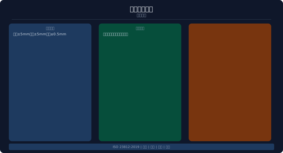
Dimensional tolerances for track installation—Permissible deviation in rail top elevation: ±5 mm (height difference between adjacent sections within any 10-meter length ≤ 3 mm); straightness of the track centerline: deviation within any 10-meter length ≤ 2 mm; permissible deviation in track span: ±5 mm (between corresponding cross-sections of the two rails) . Track joint clearance—1–2 mm for installation at ambient temperature (to allow for thermal expansion; increase by 0.5 mm for every 10°C rise in ambient temperature). The vertical difference and lateral misalignment at track joints must both be ≤0.5 mm (checked using a 300-mm straightedge).
Installation Requirements for Rail Fasteners—The spacing between rail clamps along the track is generally no greater than 600 mm (≤500 mm for heavy-duty service), and the gap between the rail clamp and the upper flange of the rail is ≤1 mm. Transition at Rail Expansion Joints—The expansion joint width is 15–20 mm, with transition rails installed on both sides (length ≥ 200 mm to ensure smooth passage of the wheels). . Installation of End Stops at Track Ends—The clearance between the end stop and the track end shall be no less than 50 mm; the height of the end stop shall be ≥ the wheel radius + 50 mm.
| Model | Track Height (mm) | Track-top width (mm) | Weight (kg/m) | Applicable Wheel Load |
|---|---|---|---|---|
| QU70 | 120 | 70 | 52.8 | ≤200 kN |
| QU80 | 130 | 80 | 63.7 | ≤300 kN |
| QU100 | 150 | 100 | 88.7 | ≤400 kN |
| QU120 | 170 | 120 | 118.1 | ≤500 kN |
Track Foundation Requirements
The track foundation should be designed based on the crane’s maximum wheel load and geological conditions—the foundation type typically consists of reinforced concrete strip foundations (the foundation width is determined by the wheel load and subgrade bearing capacity, generally ≥800 mm, with a depth of ≥600 mm). The concrete strength grade should be ≥C30, and HRB400-grade reinforcing bars should be used. Rail fastening bolts or embedded metal fittings (for welding down-clamps or welding the rails) shall be embedded in the top surface of the foundation, with a positioning accuracy of ≤2 mm. The flatness requirement for the top surface of the foundation is that the height difference over any 2-meter length along the entire length shall be ≤5 mm.
Drainage Design for Track Bases—The top surface of the base should have a drainage slope (≥1% sloping toward both sides to prevent water accumulation on the tracks), and drainage ditches or blind drains should be installed on both sides of the base. Expansion Joint Spacing for Foundations—Install one joint every 20–30 m indoors and one every 15–20 m outdoors (joint width: 20 mm; filled with asphalt-impregnated hemp fiber). The foundation should be equipped with a grounding system (grounding resistance ≤ 4 Ω), and an insulating pad should be installed between the track and the foundation (in environments with severe electrochemical corrosion). Krude Heavy Industry provides track foundation design consulting services.
Routine Maintenance and Inspections
Railway Track Routine Maintenance—Conduct monthly inspections of rail head wear (normal wear ≤ 5 mm), the tightness of rail clamps (check for loosening using a torque wrench), changes in rail joint gaps (caused by temperature fluctuations), and track surface cleanliness (free of oil stains and foreign objects). Conduct an annual full-line track inspection—track elevation (measured along the entire route using a leveling instrument), track straightness (checked using a steel wire), and track gauge (measured with a steel tape measure). Sections with excessive track wear or cracks should be replaced promptly. Krude Heavy Industries provides track inspection and replacement services.
| Inspection Items | Cycle | Methods | Evaluation Criteria |
|---|---|---|---|
| Rail-top wear | Monthly | Visual Inspection + Caliper | ≤5 mm |
| Securing the Rail Clamp | Monthly | Torque Wrench | Torque Meets Specifications |
| Joint Clearance | Every season | Feeler Gauge | 1–2 mm |
| Track Elevation | Every year | Level | ±5 mm |
| Track Gauge | Every year | Steel Tape Measure | ±5 mm |
| Straightness Along the Entire Line | Every year | Pulling a wire | ≤2 mm/10 m |
Frequently Asked Questions
Q: What are the rail types specified in ISO 23812:2019?
Answer: QU70 (52.8 kg/m), QU80 (63.7 kg/m), QU100 (88.7 kg/m), and QU120 (118.1 kg/m). Select based on maximum wheel load—QU70 is suitable for ≤200 kN, and QU120 is suitable for ≤500 kN. The material is U71Mn or U75V, with a rail head hardness of ≥260 HB.
Q: What are the main tolerance requirements for rail installation?
Answer: Elevation tolerance ±5 mm (height difference ≤3 mm within 10 m), straightness ≤2 mm/10 m, span tolerance ±5 mm. Joint gap 1–2 mm (for temperature compensation); vertical difference and lateral misalignment at joints ≤0.5 mm. Clamp spacing ≤ 600 mm (≤ 500 mm for heavy-duty applications).
Q: What are the design requirements for track foundations?
Answer: Concrete strength class C30 or higher; foundation width ≥ 800 mm; depth ≥ 600 mm. Positioning accuracy of embedded parts ≤ 2 mm. Drainage slope of the foundation top surface ≥ 1%. Expansion joint spacing: 20–30 m indoors and 15–20 m outdoors. Ground resistance ≤ 4 Ω.
Q: What is the track inspection schedule?
Answer: Monthly inspections of rail-top wear and rail clamps; quarterly inspections of joint clearances; and annual inspections of elevation, straightness, and gauge along the entire line. Rails must be replaced if wear exceeds 5 mm or if cracks are detected. Krude Heavy Industries provides track system design, installation, and inspection services.
