

Interpretation of ISO 20332:2016 “Verification of the Strength of Steel Structures Using the Limit State Method”
📌ISO 20332:2016, “Cranes—Limit State Method—Verification of the Strength of Steel Structures,” is a verification standard for the application of the limit state design method to steel structures in cranes. The standard specifies load combinations, partial factors, and strength verification methods for steel structures under the ultimate limit state and serviceability limit state.
Classification of Limit States
ISO 20332:2016 classifies the limit states of crane steel structures as follows: Ultimate Limit State (ULS—the state in which the structure reaches its maximum load-bearing capacity—including global buckling, local buckling, material yield and fracture, and fatigue fracture) , Serviceability Limit State (SLS—the state in which structural deformation or vibration exceeds permissible service limits—including excessive elastic deformation, vibration, and noise), and Fatigue Limit State (FLS—the state in which the structure undergoes fatigue failure under alternating loads). This document covers verification methods for ULS and SLS; fatigue verification is performed in accordance with ISO 24035.
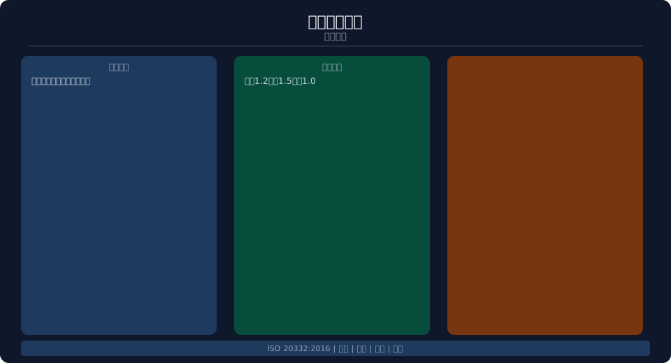
Load Combinations for ULS Verification—The loads to be considered during ULS verification for cranes include: permanent loads G (self-weight of the structure, weight of fixed equipment), variable loads Q (lift loads, wind loads, snow loads, temperature loads), and accidental loads A (seismic loads, collisions, impacts). Each load is multiplied by its corresponding partial safety factor and then combined—the basic combination is γG × G + γQ × Q, and the accidental combination is G + A + ψ × Q. The partial safety factor γG (partial safety factor for permanent loads) is taken as 1.2 (unfavorable) or 1.0 (favorable), and γQ (partial safety factor for variable loads) is taken as 1.5.
Strength Verification Methods
Basic Formula for Strength Verification—Under the combined action of design loads, the stress σd at each part of the structure must satisfy the condition σd ≤ f_d/f_M, where f_d is the design strength of the material (based on the standard yield strength divided by the material partial safety factor γM), and γM is the material partial safety factor (1.0–1.1 for steel; 1.15–1.25 for welds). For compression members, stability checks must also be performed—global stability (Euler buckling) and local stability (width-to-thickness ratio limits for plate members).
Stability Verification—The stability factor φ for compressed members is determined based on the slenderness ratio λ and the cross-section classification (Classes a, b, and c). The verification formula is N/(φ×A) ≤ f_d/γM. Global Stability of Members Under Bending — Global stability need not be verified if the lateral bracing spacing is sufficient; otherwise, it shall be verified using the formula φ_b × W × f_d / γM. Local Stability of Plates—The flange width-to-thickness ratio b/t ≤ 15 (Q235), and the web height-to-thickness ratio h₀/t_w ≤ 80 (≤ 180 when transverse stiffeners are provided). Krude Heavy Industry comprehensively adopts the limit state method in the strength design of steel structures.
| Limit State | Load Combinations | Evaluation Criteria | Sub-item Coefficient |
|---|---|---|---|
| ULS Hosting | γG × G + γQ × Q | σd ≤ fd/γM | γG = 1.2, γQ = 1.5 |
| SLS is normal | G+Q+ψ×Q | Deformation ≤ L/400 | ψ = 0.7–1.0 |
| FLS Fatigue | Stress Spectrum | D ≤ 1.0 | γF = 1.25 |
| By chance | G+A+ψ×Q | σd ≤ 1.5fd | No additional line items |
Limit States for Normal Use
SLS Verification Requirements for Deflection—Deflection at the midspan of the main girder (under rated load) ≤ L/400 to L/500 (use the stricter value for heavy-duty service); deflection at the cantilever end ≤ L/300. Relative deflection at the main and hoist crane tracks ≤ 5 mm. Maximum horizontal displacement of the structure—in the direction of the main crane’s travel ≤ H/800 (where H is the height above the rail surface); in the direction of the trolley’s travel ≤ H/500. Deformation verification uses a standard load combination (without partial factors)—G+Q (using the rated value for lifting loads and the wind pressure value for the operating condition for wind loads).
Dynamic Stiffness Requirements—The natural frequency of structural vibration when the crane starts or stops under rated load must be ≥2 Hz (to prevent operator discomfort and resonance between the operator and the load), and the structural decay time after sudden unloading of a fully loaded hoist must be ≤5 s. For cranes requiring precise positioning (such as foundry cranes), vertical stiffness requirements are even more stringent (deflection limits range from L/800 to L/1000). The steel structure design of Krude Heavy Industry cranes strictly complies with the SLS deformation and dynamic stiffness requirements.
Verification Report
The steel structure strength verification report shall include—the basis for calculations (standards and versions used), crane technical parameters (lifting capacity, span, service class, etc.), loads and load combinations (load values and combination factors for each service condition), finite element analysis or analytical calculation results (stress contour plots, deformation diagrams, and stability analysis), verification conclusions for each limit state (whether ULS and SLS meet requirements), and recommendations. The verification report must be signed by a licensed structural engineer.
| Verification Items | Requirements | Calculation Method | Report Contents |
|---|---|---|---|
| ULS Strength | σd ≤ fd/γM | Finite Element Method/Analytical Method | Stress Contour Plots + Conclusions |
| ULS Stable | N/(φA) ≤ fd/γM | Euler's Formula | Stability Verification Report |
| SLS Deformation | δmax ≤ L/400 | Deflection Calculation | Deformation Diagram |
| SLS Vibration | Fundamental frequency ≥ 2 Hz | Modal Analysis | Frequency value |
Frequently Asked Questions
Q: What are the categories of limit states defined in ISO 20332:2016?
Answer: Ultimate Limit State (ULS) for load-bearing capacity (strength/stability), Serviceability Limit State (SLS) for normal use (deflection/vibration), and Fatigue Limit State (FLS) for fatigue life. ULS and SLS use different load combinations and partial factors, respectively.
Q: How should the load partial safety factors be determined?
Answer: The partial safety factor for permanent loads is γG = 1.2 under unfavorable conditions and γG = 1.0 under favorable conditions. For variable loads, γQ = 1.5. Material partial safety factors: γM = 1.0–1.1 for steel; γM = 1.15–1.25 for welds. For accidental load combinations, G + A + ψ × Q.
Q: What are the deformation requirements for the ultimate limit state under normal use?
Answer: Main girder deflection (under rated load) ≤ L/400 (medium-duty) to L/500 (heavy-duty); cantilever end deflection ≤ L/300. Relative deflection at the rail ≤ 5 mm. The structural natural frequency must be ≥2 Hz. Deflection limits for precision-positioning cranes are even stricter.
Q: What is the formula for ULS strength verification?
Answer: σd ≤ fd/γM—where σd is the design stress (under the load combination), fd is the design strength of the material (standard yield strength), and γM is the material partial safety factor. For compression, the overall stability must also be verified: N/(φA) ≤ fd/γM. Krud Heavy Industry’s steel structure designs are verified comprehensively using the limit state method.
