

Overhead Crane Inverter Parameter Setting Table: Speed Curves and Control Mode Configuration for Hoist, Main Traverse, and Trolley
📌 Parameter Settings for Overhead Crane Inverters The system is divided into three groups of variable-frequency drives: hoist, main crane, and trolley. Each group has independent control modes, speed accuracy, and acceleration/deceleration time configurations. Based on years of experience in commissioning overhead crane electrical systems, the Krude Heavy Industry technical team recommends using closed-loop vector control (with encoder feedback) for the hoist inverter, with a speed accuracy of ≤0.01%; for the main and auxiliary travel inverters, open-loop vector control is recommended, with a speed accuracy of ≤0.5%. Correct parameter configuration is the foundation for the reliable operation of the overhead crane’s electrical system.
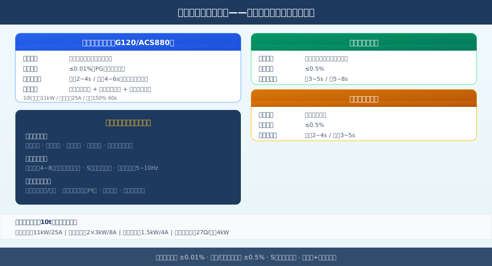
The parameter settings for overhead crane inverters involve independent drive configurations for three sets of motors: hoist, main girder, and trolley. The figure below, based on a 10-metric-ton overhead crane, illustrates the complete parameter configuration scheme for the hoist, main-girder, and trolley inverters. The parameter configuration for overhead crane inverters involves key aspects such as automatic motor parameter tuning, multi-speed/analog speed curve configuration, acceleration and deceleration time settings, braking modes, and protection parameter configuration. Standard configuration for a 10-metric-ton overhead crane: hoist drive 11 kW/25 A, main girder drive 2 × 3 kW/8 A, and trolley drive 1.5 kW/4 A.
Autotuning of Motor Parameters
The first step in setting up an inverter is automatic motor parameter tuning, which ensures that the inverter’s motor model matches the actual motor parameters. Automatic tuning is divided into two methods: static tuning and dynamic tuning. Static tuning measures the stator resistance and leakage inductance while the motor is not rotating; it is suitable for travel drive inverters. Dynamic tuning measures the full set of motor parameters while the motor is rotating under no-load conditions; it is suitable for hoist drive inverters to achieve higher speed control accuracy.
💬 Comment from the Technical Director at Krude Heavy Industries:
“Autotuning of motor parameters is the foundation of variable frequency drive parameter configuration; many on-site failures are caused by incorrect input of nameplate parameters or omitting the autotuning step. During factory commissioning at Krude Heavy Industry, we require that the hoisting inverter for every overhead crane undergo dynamic self-tuning. Upon completion of the tuning, the deviation between the calculated resistance value and the measured value must be ≤3%—a standard stricter than the industry requirement of 5%—to ensure the reliability of low-frequency, high-torque output. ”
Before self-tuning, you must correctly enter the motor nameplate parameters into the variable frequency drive: Rated voltage (380 V/50 Hz), rated current (as indicated on the motor nameplate), rated speed (typically 960 or 1440 rpm for the YZR series), power factor (0.78–0.85), and rated power. Incorrect motor parameter input may result in insufficient output torque, overcurrent, or speed deviations exceeding the specified limits. After tuning is complete, save the parameters and compare them with the motor’s actual parameters to verify accuracy.
Speed Setting and Control Mode Configuration
The speed control modes for overhead crane variable-frequency drives include multi-speed and analog setpoint control. The multi-speed mode selects fixed speed settings through a combination of the PLC’s digital output terminals. For the hoisting mechanism, a 4–8-speed configuration is recommended (5 Hz for low-speed crawling, 25 Hz for medium-speed operation, and 50 Hz for rated speed), while 2–4 speeds are recommended for the main and auxiliary trolleys. The analog control mode achieves stepless speed regulation via 0–10 V or 4–20 mA signals output by the PLC, making it suitable for hoisting control and anti-sway control applications that require high speed accuracy.
The speed curve must be configured with S-curve acceleration and deceleration times, as well as an arc transition for the initial segment. The hoisting mechanism’s acceleration time is 2–4 seconds, and the deceleration time is 4–6 seconds (the deceleration segment is longer than the acceleration segment to reduce the risk of hook sway). Set the S-curve time for the initial segment to 0.2–0.5 seconds to ensure a smooth start and stop, thereby reducing load sway. Example parameters for acceleration and deceleration times: Set P1120 (G120 acceleration time) to 3.0 s and P1121 (deceleration time) to 5.0 s. Gantry acceleration time: 3–5 seconds; deceleration time: 5–8 seconds; trolley acceleration time: 2–4 seconds; deceleration time: 3–5 seconds.
Braking System Configuration
The braking system of an overhead crane consists of a mechanical brake (brake shoe) and an electrical brake controlled by a variable frequency drive (VFD); the two must be interlocked and operate in coordination. There are three types of electrical braking via a variable frequency drive (VFD): DC injection braking, dynamic braking resistors, and regenerative braking. The most common method used in overhead cranes is DC injection braking combined with an external braking resistor, in which the motor’s regenerative energy is dissipated as heat through the braking resistor during the VFD deceleration process.
Braking Resistor Selection Parameters: Select the resistance value according to the recommendations in the inverter manual (27Ω is commonly used for the G120 series); calculate the power based on the hoisting mechanism’s braking frequency (number of braking operations per hour × energy per braking operation). The recommended braking resistor power should be 20%–30% of the inverter’s rated power. Interlocking of the opening and closing sequences for mechanical brakes (brake shoes): The inverter sends a signal to open the brake shoes after establishing output torque; before the inverter stops outputting power, it first closes the brake shoes and then removes the torque to prevent hook slippage. The brake release delay is recommended to be set between 0.2 and 0.5 seconds, and the brake engagement delay is recommended to be set between 0.1 and 0.3 seconds.
Braking resistor overheating protection parameters: Set the braking resistor temperature model (P0530 series parameter); when the resistor surface temperature exceeds 200°C, the inverter will report a fault and stop. Set the duty cycle limit for the braking chopper to 100%. For detailed maintenance and adjustment procedures for the brake, refer to the “Brake Inspection” section in the article on daily crane maintenance.
Protection Function Parameter Configuration
Proper configuration of the variable frequency drive’s protection functions can prevent damage and failures in electrical equipment rated at 80% or higher. Key protection parameters include: motor overload protection (I²t model electronic thermal relay, with the current threshold set to 110% of the motor’s rated current; trip time class Class 10 is suitable for frequent starting and braking operations in cranes), overvoltage protection (DC bus overvoltage threshold for 820V/380V systems; if exceeded, current is limited and speed reduced, or a fault is reported and the system stops), phase loss protection (both input and output phase loss must be enabled, with a detection time of 0.5 seconds), and ground fault protection (when enabled, the inverter monitors for leakage current to ground on the output side).
💬 Comment from the Technical Director at Krude Heavy Industries:
“Proper configuration of protection parameters is the key to ensuring the long-term, stable operation of a variable frequency drive. Before each overhead crane leaves the factory, Krude Heavy Industry verifies the functions of overload protection, phase loss protection, and ground fault protection item by item, with particular attention to the braking resistor overheating protection and speed deviation monitoring for the hoisting mechanism. If these two parameters are set improperly, they can easily lead to equipment damage or even safety incidents during high-frequency lifting operations. We recommend that users check the status of these protection parameters quarterly.”
Other Protection Parameters: Motor Stall Protection (triggers a fault within 1 second if the stall current exceeds the rated value of 200%), Inverter Overheat Protection (derated operation when the heat sink temperature exceeds 85°C; triggers a fault and stops the system at 90°C), Speed Deviation Monitoring (a fault is reported if the deviation between the setpoint and actual value exceeds ±5% and persists for 3 seconds), load torque monitoring (used for overload detection; a fault is reported if the torque exceeds 150% of the rated value). The fault response for all protection parameters is set as follows: the hoisting mechanism output is cut off + the mechanical brake is engaged, and the main and trolley mechanisms decelerate to a stop.
Comparison Table of Inverter Parameters for Hoist and Trolley Motors
Parameter Items Hoist Inverter Frequency Inverters for Heavy-Duty Vehicles Inverter for Small Vehicles Control Mode Closed-Loop Vector Control (with Encoder) Open-Loop Vector Control Open-Loop Vector Control Speed Accuracy ≤0.011 TP3T ≤0.51 TP3T ≤0.51 TP3T Acceleration Time 2–4 seconds 3–5 seconds 2–4 seconds Deceleration time 4–6 seconds 5–8 seconds 3–5 seconds 10-metric-ton power configuration 11 kW/25 A 2 × 3 kW / 8 A 1.5 kW/4 A Speed Control Methods 4–8 speed settings + analog control 2–4 speed settings 2–4 speed settings Braking System DC Injection + Braking Resistor + Mechanical Brake DC Injection Braking DC Injection Braking Overload Protection Threshold Rated Current 110% / Class 10 Rated Current 110% / Class 10 Rated Current 110% / Class 10 Braking Resistor Resistance 27 Ω / 4 kW Comes standard with built-in Comes standard with built-in
Motor Self-Tuning Procedure
First, enter the motor nameplate parameters (rated voltage, current, speed, and power factor) → perform static tuning (main hoist/auxiliary hoist) → perform dynamic tuning (hoisting). After tuning, compare the calculated values with the nameplate values; the deviation must be ≤5%.
Multi-speed configuration
Hoist: 4–8 speed ranges: low-speed creep at 5 Hz, medium-speed operation at 25 Hz, and high speed at 50 Hz. Main and auxiliary hoists: 2–4 speed ranges: low speed at 10 Hz and high speed at 50 Hz. The PLC selects the speed range via a combination of DI terminals.
S-shaped acceleration and deceleration curve
Set an S-shaped arc transition of 0.2 to 0.5 seconds at the start of acceleration and deceleration to ensure smooth starts and stops and reduce load sway. Hoisting: P1120 = 3.0 s / P1121 = 5.0 s; Trolley: P1120 = 4.0 s / P1121 = 6.0 s.
Brake Interlock Timing Sequence
The variable frequency drive opens the brake (with a delay of 0.2–0.5 s) after torque is established, and closes the brake before stopping output, then removes the torque (with a delay of 0.1–0.3 s). The brake-release signal is transmitted from the variable frequency drive to the PLC via a relay output, providing interlock protection.
PROFINET Communication Parameters
Inverter station address settings (1–3 correspond to hoist, main trolley, and auxiliary trolley, respectively), PROFINET device name configuration, 16-bit PZD1 control word/status word, and PZD2 speed setpoint/actual value.
Common Parameter Errors
Motor rated current set too high → Overload protection does not activate, causing the motor to burn out. Acceleration time too short → Overcurrent trip. Speed deviation monitoring disabled → Runaway when the encoder cable is disconnected. Braking resistor power insufficient → Overheating and burnout.
Frequently Asked Questions (FAQ)
Q: How do I set the acceleration and deceleration times for an overhead crane’s variable-frequency drive?
Answer: The acceleration and deceleration times for the overhead crane’s variable-frequency drive are set based on the characteristics of the hoisting mechanism and the load conditions. For the hoisting mechanism, acceleration is 2–4 seconds and deceleration is 4–6 seconds (deceleration takes longer than acceleration to prevent hook slippage); for the main girder, acceleration is 3–5 seconds and deceleration is 5–8 seconds; and for the trolley, acceleration is 2–4 seconds and deceleration is 3–5 seconds. An S-shaped arc of 0.2–0.5 seconds is set at the beginning of the acceleration and deceleration phases to ensure a smooth transition. After parameter settings are configured, verify under 50% and 100% loads that the braking slip is ≤ v/100.
Q: What causes an overcurrent fault in an overhead crane inverter?
Answer: Common causes of overcurrent faults in overhead crane variable-frequency drives: ① The acceleration time is set too short, resulting in excessive current surges; ② Motor parameter autotuning has not been performed or the parameters are inaccurate; ③ The drive outputs while the brake is not released (brake sticking or incorrect interlock timing); ④ Damaged insulation in the motor windings or cables. Troubleshooting sequence: First, check the insulation on the motor side → then check the brake status → verify the acceleration time setting → perform motor autotuning again. In accordance with GB/T 5226.1-2019, operation may only resume after a no-load verification following fault resolution.
Q: Why is closed-loop vector control used in hoist inverters for overhead cranes?
Answer: The hoisting mechanism of an overhead crane places extremely high demands on speed control accuracy and torque response. Closed-loop vector control uses real-time feedback from an encoder to measure the motor’s actual speed, achieving a speed accuracy of ≤0.01%. Even at zero speed, it can output 150% of rated torque to keep the load stationary. Open-loop vector control suffers from insufficient torque output at low frequencies (≤5 Hz), which can easily lead to insufficient lifting power or hook slippage. Since the speed accuracy requirements for the main and auxiliary hoists are lower, open-loop vector control is sufficient to meet the accuracy requirement of ≤0.5%.
Q: How do you select a braking resistor for an overhead crane inverter?
Answer: The braking resistor for an overhead crane’s variable frequency drive (VFD) should be selected based on the resistance value recommended in the VFD manual. In its standard configuration for a 10-metric-ton overhead crane, Krude Heavy Industry uses a G120 series hoisting VFD (11 kW) paired with a 27 Ω/4 kW braking resistor. The power rating of the braking resistor is calculated based on the hoisting mechanism’s braking frequency: number of braking operations per hour × energy per braking operation. The recommended power rating is 20%–30% of the inverter’s rated power. The braking resistor must be installed on the top or side of the cabinet in a well-ventilated area and equipped with temperature protection (surface temperature ≤ 200°C). For the maintenance schedule of the brake, refer to the brake inspection section in the crane maintenance manual.
| Parameter Items | Hoist Inverter | Frequency Inverters for Heavy-Duty Vehicles | Inverter for Small Vehicles |
|---|---|---|---|
| Control Mode | Closed-Loop Vector Control (with Encoder) | Open-Loop Vector Control | Open-Loop Vector Control |
| Speed Accuracy | ≤0.011 TP3T | ≤0.51 TP3T | ≤0.51 TP3T |
| Acceleration Time | 2–4 seconds | 3–5 seconds | 2–4 seconds |
| Deceleration time | 4–6 seconds | 5–8 seconds | 3–5 seconds |
| 10-metric-ton power configuration | 11 kW/25 A | 2 × 3 kW / 8 A | 1.5 kW/4 A |
| Speed Control Methods | 4–8 speed settings + analog control | 2–4 speed settings | 2–4 speed settings |
| Braking System | DC Injection + Braking Resistor + Mechanical Brake | DC Injection Braking | DC Injection Braking |
| Overload Protection Threshold | Rated Current 110% / Class 10 | Rated Current 110% / Class 10 | Rated Current 110% / Class 10 |
| Braking Resistor Resistance | 27 Ω / 4 kW | Comes standard with built-in | Comes standard with built-in |
Motor Self-Tuning Procedure
First, enter the motor nameplate parameters (rated voltage, current, speed, and power factor) → perform static tuning (main hoist/auxiliary hoist) → perform dynamic tuning (hoisting). After tuning, compare the calculated values with the nameplate values; the deviation must be ≤5%.
Multi-speed configuration
Hoist: 4–8 speed ranges: low-speed creep at 5 Hz, medium-speed operation at 25 Hz, and high speed at 50 Hz. Main and auxiliary hoists: 2–4 speed ranges: low speed at 10 Hz and high speed at 50 Hz. The PLC selects the speed range via a combination of DI terminals.
S-shaped acceleration and deceleration curve
Set an S-shaped arc transition of 0.2 to 0.5 seconds at the start of acceleration and deceleration to ensure smooth starts and stops and reduce load sway. Hoisting: P1120 = 3.0 s / P1121 = 5.0 s; Trolley: P1120 = 4.0 s / P1121 = 6.0 s.
Brake Interlock Timing Sequence
The variable frequency drive opens the brake (with a delay of 0.2–0.5 s) after torque is established, and closes the brake before stopping output, then removes the torque (with a delay of 0.1–0.3 s). The brake-release signal is transmitted from the variable frequency drive to the PLC via a relay output, providing interlock protection.
PROFINET Communication Parameters
Inverter station address settings (1–3 correspond to hoist, main trolley, and auxiliary trolley, respectively), PROFINET device name configuration, 16-bit PZD1 control word/status word, and PZD2 speed setpoint/actual value.
Common Parameter Errors
Motor rated current set too high → Overload protection does not activate, causing the motor to burn out. Acceleration time too short → Overcurrent trip. Speed deviation monitoring disabled → Runaway when the encoder cable is disconnected. Braking resistor power insufficient → Overheating and burnout.
Frequently Asked Questions (FAQ)
Q: How do I set the acceleration and deceleration times for an overhead crane’s variable-frequency drive?
Answer: The acceleration and deceleration times for the overhead crane’s variable-frequency drive are set based on the characteristics of the hoisting mechanism and the load conditions. For the hoisting mechanism, acceleration is 2–4 seconds and deceleration is 4–6 seconds (deceleration takes longer than acceleration to prevent hook slippage); for the main girder, acceleration is 3–5 seconds and deceleration is 5–8 seconds; and for the trolley, acceleration is 2–4 seconds and deceleration is 3–5 seconds. An S-shaped arc of 0.2–0.5 seconds is set at the beginning of the acceleration and deceleration phases to ensure a smooth transition. After parameter settings are configured, verify under 50% and 100% loads that the braking slip is ≤ v/100.
Q: What causes an overcurrent fault in an overhead crane inverter?
Answer: Common causes of overcurrent faults in overhead crane variable-frequency drives: ① The acceleration time is set too short, resulting in excessive current surges; ② Motor parameter autotuning has not been performed or the parameters are inaccurate; ③ The drive outputs while the brake is not released (brake sticking or incorrect interlock timing); ④ Damaged insulation in the motor windings or cables. Troubleshooting sequence: First, check the insulation on the motor side → then check the brake status → verify the acceleration time setting → perform motor autotuning again. In accordance with GB/T 5226.1-2019, operation may only resume after a no-load verification following fault resolution.
Q: Why is closed-loop vector control used in hoist inverters for overhead cranes?
Answer: The hoisting mechanism of an overhead crane places extremely high demands on speed control accuracy and torque response. Closed-loop vector control uses real-time feedback from an encoder to measure the motor’s actual speed, achieving a speed accuracy of ≤0.01%. Even at zero speed, it can output 150% of rated torque to keep the load stationary. Open-loop vector control suffers from insufficient torque output at low frequencies (≤5 Hz), which can easily lead to insufficient lifting power or hook slippage. Since the speed accuracy requirements for the main and auxiliary hoists are lower, open-loop vector control is sufficient to meet the accuracy requirement of ≤0.5%.
Q: How do you select a braking resistor for an overhead crane inverter?
Answer: The braking resistor for an overhead crane’s variable frequency drive (VFD) should be selected based on the resistance value recommended in the VFD manual. In its standard configuration for a 10-metric-ton overhead crane, Krude Heavy Industry uses a G120 series hoisting VFD (11 kW) paired with a 27 Ω/4 kW braking resistor. The power rating of the braking resistor is calculated based on the hoisting mechanism’s braking frequency: number of braking operations per hour × energy per braking operation. The recommended power rating is 20%–30% of the inverter’s rated power. The braking resistor must be installed on the top or side of the cabinet in a well-ventilated area and equipped with temperature protection (surface temperature ≤ 200°C). For the maintenance schedule of the brake, refer to the brake inspection section in the crane maintenance manual.
