Wire Rope Drum Specs for Overhead Cranes: Diameter, Length & Groove

Key Point The wire rope drum is the cylindrical component in the crane's hoisting mechanism that spools the wire rope. ① Drum diameter D ≥ wire rope diameter d × 20 (ISO 4301 Crane Design Standard); Kelude Heavy Industry adheres to the stricter D ≥ d × 25 criterion. ② Drum wall thickness δ ≥ 0.8d and ≥ 12 mm. ③ A minimum of 3 safety wraps of wire rope must remain on the drum. ④ Kelude drums are fabricated from Q355B (≈S355JR) steel plate, rolled and welded, with the rope grooves hardened via medium-frequency induction hardening to HRC40–45.

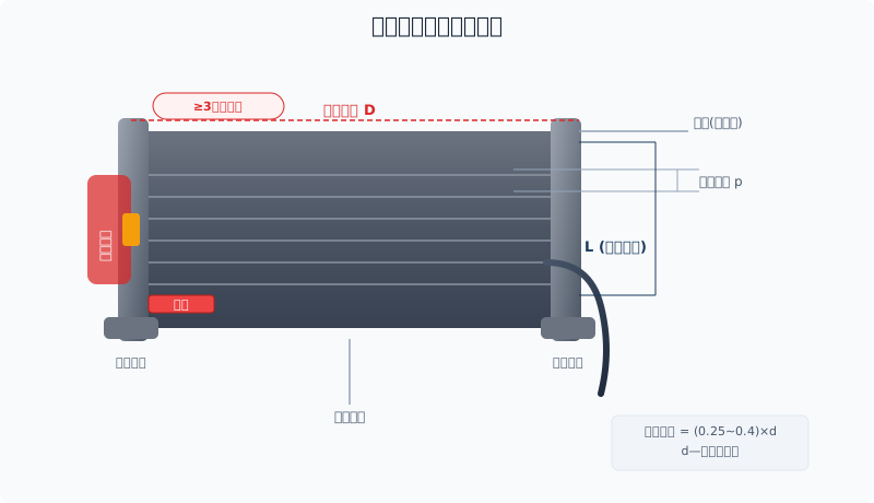
Wire Rope DrumstructureSchematic Diagram:shell,Wheel flange,rope groove,wire rope clipandsafety wrapsAnnotations

Drum Construction and Specifications

The drum assembly consists of the barrel, left and right wheel flanges (rope guard plates), rope grooves, and wire rope clips. The drum connects to the gear motor through a coupling, with the wire rope wound sequentially along the rope grooves. Drum diameter, overall length, and groove dimensions must be precisely matched to the wire rope diameter and lifting height. While ISO 4301 Crane Design Standard specifies a drum diameter ratio of D ≥ d × 20, Kelude Heavy Industry applies the more demanding D ≥ d × 25 to extend wire rope fatigue life. The overall drum length L is determined by the total wire rope length, the number of winding layers, and the rope groove pitch.

wire rope diameterd(mm) drum diameter D(mm) Drum Length L(mm) rope groove Pitchp(mm) wall thicknessδ(mm) Application Lifting Height(m)
8 200 300~400 10 12 ≤12
11 300 400~550 13 14 ≤18
13 350 500~700 16 16 ≤24
15 400 600~850 18 18 ≤30
17.5 500 750~1000 21 20 ≤36
21.5 600 900~1300 25 22 ≤42
26 750 1100~1600 30 25 ≤50
32 900 1400~2000 36 28 ≤60

Note: Drum diameter D is calculated as D ≥ d × 25, and wall thickness δ as ≥ 1.0 × d, with a minimum of 12 mm. Kelude drums are manufactured from Q355B steel plate, rolled and welded, with the rope grooves medium-frequency induction hardened.

Drum Diameter and Length Engineering Calculation

The drum diameter D is determined according to ISO 4301 Crane Design Standard, which requires D ≥ d × 20 (where d is the wire rope diameter). Kelude Heavy Industry adheres to a more stringent D ≥ d × 25. The drum length L is determined by the total length of wire rope to be spooled, the number of winding layers, and the rope groove pitch.

Example 1: Given a wire rope diameter d = 15 mm, lifting height H = 24 m, rope reeving m = 4, and 3 safety wraps retained on the drum. Calculate the drum diameter and length.
Solution:
① Drum diameter D ≥ 25 × 15 = 375 mm, select standard D = 400 mm.
② Rope groove pitch p = d + 3 = 18 mm.
③ Total wire rope length L₀ = H × m + safety wraps × πD = 24 × 4 + 3 × 3.14 × 0.4 = 96 + 3.77 ≈ 100 m.
④ Number of wraps per layer n = L / (p × πD) = 100 / (0.018 × 3.14 × 0.4) ≈ 4422 wraps. If the drum length is L = 600 mm, the wraps per layer = L / p = 600 / 18 ≈ 33 wraps, requiring winding layers = 4422 / 33 ≈ 134 layers... This is clearly impractical.
⑤ Correction: Adopt multi-layer winding. Set drum body length L = 800 mm. Wraps per layer = 800 / 18 ≈ 44 wraps. Required layers = L₀ × p / (πD × L) = 100 × 0.018 / (3.14 × 0.4 × 0.8) ≈ 1.79 layers, use 2 layers.

Example 2: For a 32t Double-Girder Bridge Crane with wire rope d = 21.5 mm, lifting height H = 30 m, rope reeving m = 6, drum diameter D ≥ 25 × 21.5 = 537.5 mm, select standard D = 600 mm. Rope groove pitch p ≈ 25 mm, drum length L = 1000 mm, wraps per layer = 1000 / 25 = 40. The actual required layers are calculated based on the total rope length, designed for 2 layers of winding.

Drum Wall Thickness Calculation and Strength Verification

The drum wall thickness δ is typically calculated using the empirical formula δ ≥ 0.8d and ≥ 12 mm (where d is the wire rope diameter). Kelude Heavy Industry designs with δ ≥ 1.0d, providing a greater safety margin. Precise wall thickness calculation must consider the radial pressure and bending stress induced by the wound wire rope:
Radial compressive stress σ = 0.5Fₘₐₓ / (δ × p), where Fₘₐₓ is the maximum wire rope tension.
Allowable stress [σ] = σₛ / n. For Q355B steel, the yield strength σₛ ≥ 355 MPa, and with a safety factor n ≥ 1.5, the allowable stress [σ] ≤ 236 MPa.

Example 3: Given a maximum wire rope tension Fₘₐₓ = 50 kN, drum wall thickness δ = 20 mm, and rope groove pitch p = 25 mm.
σ = 0.5 × 50000 / (20 × 25) = 50 MPa < 236 MPa, therefore the strength requirement is satisfied.

Drum Manufacturing Process and Inspection

Kelude Heavy Industry's drum manufacturing process: ① Cutting of Q355B steel plate ② Plate bending machine rolling to form the cylinder (roundness tolerance ≤ 1 mm) ③ Longitudinal seam welding (submerged arc automatic welding, wire H10Mn2) ④ Non-destructive testing of welds (Ultrasonic Testing (UT) + Magnetic Particle Inspection (MPI), weld quality level Ⅱ acceptable) ⑤ Machining of flange faces and spigots on both ends ⑥ Rope groove machining (CNC lathe) ⑦ Medium-frequency induction hardening of rope grooves (HRC 40~45, hardened layer depth ≥ 2 mm) ⑧ Assembly of Drum Coupling and Bearing Housing ⑨ Static load test with 1.5 times rated load on each unit before delivery. Each drum is supplied with a weld inspection report and a dimensional inspection report.

Common drum welding defects and prevention: ① Welding cracks — Preheating temperature ≥ 100°C (for plate thickness > 20 mm), post-weld slow cooling for stress relief; ② Porosity — Ensure proper drying of welding electrodes/flux, clean oil and rust from the groove before welding; ③ Incomplete penetration — Ensure correct groove angle and root face dimensions, and adjust welding parameters.

Drum Coupling and Support Structure

The drum is connected to the gearbox output shaft via a Drum Coupling. For large tonnage drums, one end utilizes a GIICL type crowned gear coupling (compensating for angular misalignment ≤ 1.5°), while the other end is supported by a spherical roller bearing. The Drum Coupling must withstand the radial load from the drum's dead weight and wire rope tension. Model selection is based on the transmitted torque multiplied by a safety factor of 1.5.

Example 4: Drum input torque T = 20000 N·m, safety factor 1.5, selection torque T₀ = 20000 × 1.5 = 30000 N·m. Consulting the GIICL series model table, GIICL8 with a nominal torque (Tn) of 31500 N·m ≥ 30000 N·m. Therefore, select the GIICL8 coupling (bore diameter range 90~150 mm). Kelude Heavy Industry drum couplings feature gear teeth that are carburized and quenched to HRC 58~62, offering excellent Wear Resistance.

Drum Selection Precautions

1
Diameter Ratio D/d
ISO 4301 requires D/d ≥ 20, while Kelude adheres to D/d ≥ 25. A larger D/d ratio results in lower bending stress on the wire rope and a longer fatigue life.
2
Safety Wraps
A minimum of 3 safety wraps must remain on the drum (per ISO 4301), even when the hook is lowered to its lowest working position.
3
Wall Thickness Calculation
Drum wall thickness δ ≥ 0.8d (d = wire rope diameter) and ≥ 12 mm. Kelude Heavy Industry designs with 1.0 × d, providing a larger safety margin.
4
Rope Groove Dimensions
Rope groove pitch p = d + 2~4 mm, groove depth h = (0.25~0.4) × d. Incorrect groove dimensions can accelerate wire rope wear.
5
Multi-Layer Winding
For multi-layer winding, the drum length and number of winding layers must be optimized to prevent rope misalignment and excessive wear.
6
Material and Heat Treatment
Q355B steel is standard for its strength and weldability. Induction hardening of the rope grooves significantly enhances surface wear resistance.
Wire Rope Fleet Angle
The fleet angle of the wire rope entering the drum must not exceed 3.5°. Excessive fleet angles can cause rope entanglement, uneven groove wear, and wire rope derailment.
6
Drum Material
Kelude drums are fabricated from Q355B (≈S355JR) steel plate with welded construction, offering a tensile strength of ≥470 MPa. The rope grooves undergo medium-frequency induction hardening (HRC40–45), delivering twice the wear resistance of standard drums.

FAQ

Q: Why are 3 safety wraps required on the drum?

A: Safety wraps prevent the wire rope clip from bearing the full tensile load. When the hook is at its lowest position, the three wraps of rope at the clip provide friction and cushioning, preventing the clip from slipping. This is a mandatory requirement under ISO 4301 Crane Design Standard. Kelude marks the safety wrap zone with a red color code on the drum for clear identification.

Q: When should a drum groove be replaced due to wear?

A: The drum must be replaced when groove depth wear reaches 25% of the original dimension, or when wall thickness wear at the groove bottom reaches 15% of the original dimension. Kelude drum grooves are medium-frequency induction hardened, providing more than twice the service life of standard drums. If daily inspection reveals loose rope fit in the groove, abnormal noise, or visible step-like wear, stop the crane immediately and inspect.

Q: How do I troubleshoot abnormal noise and rope entanglement on the drum?

A: Abnormal drum noise can result from: ① damaged or under-lubricated bearings; ② wire rope derailment or cross-winding; ③ coupling coaxiality deviation; ④ cracks in the drum shell. Rope entanglement is typically caused by excessive fleet angle, a faulty rope guide, or improper operation. Kelude recommends first checking the fleet angle (≤3.5°) and rope guide condition, then inspecting the bearings and coupling.

Q: How is drum diameter calculated? Can it be increased?

A: Drum diameter D ≥ d × 20 (lower limit per ISO 4301 Crane Design Standard). Increasing the drum diameter reduces bending stress on the wire rope and extends its service life, but it also raises the lifting speed (v = πDn — a larger D means faster rope travel at the same rotational speed). Kelude offers custom non-standard drum diameters, which require recalculating motor power and speed ratio.

This completes the technical guide to crane wire rope drum specifications and selection. Kelude supplies a full range of Q355B welded drums and customization services, including non-standard diameters, lengths, and rope groove dimensions. For drum design calculations or selection assistance, contact the Kelude technical team.

Related News

contact

contact us

phone:
+86 13903802779

mail:3915269@qq.com

Working hours: Monday to Friday

Wechat
Wechat
SHARE
TOP