GB/T 31051.1-2014 Crane Terminology and Classification Standard

GB/T 31051.1-2014 "Cranes — Terminology and Classification — Part 1: General Terms" is the foundational standard for the crane terminology classification system. It defines the basic crane classification methods, general terms, and definitions, covering classification frameworks based on structural type, mode of operation, and hoisting mechanism type.

GB/T 31051.1-2014 serves as the base general standard within the crane terminology and classification series, providing unified specifications for crane term definitions and classification systems. The standard covers crane definitions, basic types, and classification methods, making it a cornerstone document for the entire crane industry. This article provides a systematic review of the standard's core content.

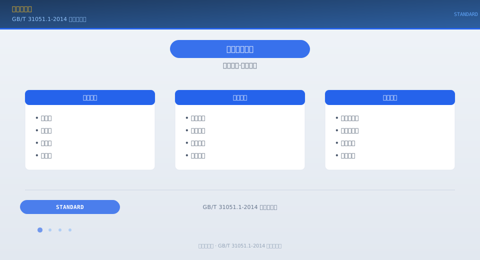
GB/T 31051.1-2014 crane terminology and classification standard


Standard Positioning and Classification Framework

GB/T 31051.1-2014 is Part 1 of the GB/T 31051 "Cranes — Terminology and Classification" series and a key component of the fundamental crane standards system. Unlike the GB/T 6974 series, which focuses on type-specific terminology, GB/T 31051.1 addresses crane classification from multiple dimensions. By structural type, cranes fall into three main categories: overhead type cranes (bridge, gantry, semi-gantry), jib type cranes (tower, mobile, portal, mast, floating, etc.), and cable type cranes (cable cranes). By mobility, cranes are classified as fixed base, mobile, or self-propelled. By hoisting mechanism, they are grouped into wire rope type, hydraulic cylinder type, and electric hoist type cranes.

Crane Classification Dimensions

The standard classifies cranes along the following dimensions: By bridge girder configuration — single-girder bridge cranes, double-girder bridge cranes (further divided into box girder, truss girder, etc.), single-girder gantry cranes, and twin-girder gantry cranes. By boom structure — trolley-luffing tower cranes, luffing-jib tower cranes, truck cranes, crawler cranes, all-terrain cranes, rough-terrain cranes (single cab, 4WD, pick-and-carry), portal cranes, mast cranes, floating cranes, railway cranes, deck cranes, and cantilever cranes. By load-handling device — hook cranes, grab cranes (clamshell cranes), electromagnetic cranes (lifting electromagnets), combination hook-grab cranes, and metallurgical specialty cranes (for ladles, clamps, charging, casting, etc.). By work duty — Class A1 through A8 cranes. The standard also categorizes cranes by application environment, including workshop cranes, warehouse cranes, yard cranes, shipyard cranes, harbor cranes, and construction tower cranes.

Three Main Types
Overhead / Jib / Cable
By Mobility
Fixed / Mobile / Self-Propelled
By Load-Handling Device
Hook / Grab / Electromagnet / Metallurgical
By Work Duty
A1~A8 Utilization + Load
By Application
Workshop / Warehouse / Port Shipyard / Construction
Hook Pulley Ratio
Ratio = Pulley Block Rope Parts

General Term Definitions

The standard provides precise definitions for general crane terminology: Rated lifting capacity — the maximum load a crane is permitted to lift, including the weight of the load-handling device. Span — the horizontal distance between the centerlines of the bridge runway rails of an overhead type crane. Working radius — the horizontal distance from the slewing centerline of a jib type crane to the vertical line of the load-handling device. Load moment — the product of the lifting capacity and the corresponding working radius, serving as a comprehensive indicator of a jib type crane's lifting capability. Work duty — a combined classification indicator reflecting both the degree of full-load usage and the frequency of operation, determined by the combination of utilization class (U0–U9) and load spectrum (Q1–Q4). Lifting height — the vertical distance from the ground to the highest position of the hook. Load-lowering height — the vertical distance from the ground to the lowest position of the hook, applicable to cranes serving below-grade areas. Hook pulley ratio — the number of hoisting rope parts wound on the movable pulley block; a higher ratio increases the rated lifting capacity but reduces the lifting speed.

Relationship Within the Terminology Standard System

GB/T 31051.1-2014 and the GB/T 6974 series serve complementary roles. The GB/T 6974 series is organized by crane type (Part 1: general principles, Part 2: mobile cranes, Part 3: tower cranes, Part 5: bridge and gantry cranes) and focuses on defining the structural and mechanism terminology specific to each type. The GB/T 31051 series, by contrast, addresses the classification framework itself — answering "how cranes should be classified" and "what defines the boundaries between crane types." Together, these two series form the twin pillars of the crane terminology standard system: GB/T 31051.1 first establishes the category to which a crane belongs, and the corresponding part of GB/T 6974 then provides the detailed term definitions for that specific type. The Kelude technical team applies this classification framework when discussing product selection with customers, ensuring accurate and unambiguous machine descriptions.


Crane Terminology and Classification Reference Table

The reference table below lists the core parameter configurations of the crane terminology and classification standard for the convenience of selection and operating personnel.

Kelude Heavy Industry: Engineered for the Toughest Lifting Challenges

Kelude Heavy Industry is a specialized manufacturer of heavy-duty industrial cranes and hoisting solutions. We focus on the design and production of overhead traveling cranes, gantry cranes, and electric hoists, delivering reliable performance for demanding applications across manufacturing, logistics, and energy sectors.

Frequently Asked Questions

Q: What is your lead time for a standard double-girder overhead crane?
A: Typical lead time is 8–12 weeks after approval of the general arrangement drawing, depending on capacity and customization level.

Q: Do you provide cranes for explosion-proof environments?
A: Yes, we offer explosion-proof configurations with certified electrical components and sealed enclosures, suitable for Zone 1 and Zone 2 hazardous areas.

Q: Can you retrofit an existing crane with a new hoist or control system?
A: Absolutely. We supply hoists, end carriages, and control panels that can be integrated into most existing crane structures, improving safety and performance without full replacement.

← Scroll left / right to view full table →
Classification DimensionCategory NameDefinition DescriptionTypical Models
Bystructural typeBridge/Gantry/Tower/BoomMain Girder Structure+Support ModeQD/LH/MG/QTZ
By ApplicationGeneral Purpose/Metallurgical/Explosion-proof/insulationSpecialenvironmental adaptabilityYZB/BQ/BY
By MobilityFixing Bridge/MobileMobilityGantry Crane/Rubber-Tyred Gantry (RTG)
By Hoisting mechanismHoist Bridge/Hoist Winch BridgeHoisting / Liftingdrive modeCD1/QD

FAQ

Q: What is the main difference between an overhead type crane and a jib type crane?
A: The structural feature of an overhead type crane (bridge crane, gantry crane) is that the bridge girder is supported directly on crane rails via the travel mechanism (bridge crane) or on ground rails through outriggers (gantry crane). The load is lifted vertically beneath the bridge girder and moves horizontally along the main girder with the trolley. The structural feature of a jib type crane (tower crane, mobile crane, portal crane, etc.) is that lifting and luffing are achieved through the jib (boom), which can rotate 360° around the slewing center. Simply put: an overhead type crane moves in two dimensions along the rails (hoisting + trolley + crane bridge), while a jib type crane can position loads anywhere in three-dimensional space (hoisting + slewing + luffing). For selection: choose an overhead type crane when straight-line lifting is needed within a limited factory building space; choose a jib type crane when all-around operation in an open area is required.
Q: How are crane work duty classifications A1–A8 determined?
A: The work duty classification is determined by two factors: the utilization class and the load spectrum. The utilization class, designated U0–U9, reflects how frequently the crane is used, based on the total number of working cycles (U0: ≤16,000 cycles; U9: ≥5 million cycles). The load spectrum, designated Q1–Q4, indicates the severity of loads the crane handles, where Q1 means the crane rarely operates at full load and Q4 means it frequently operates at full load. The combination of these two factors yields the work duty level via a reference table. For example, U5 (320,000–630,000 cycles) combined with Q2 (average load between 1/8 and 1/3 of the rated load) corresponds to classification A4. Typical applications include: A3 and below for maintenance and installation work, A4–A5 for general workshop and warehouse duty, A6 for heavy-duty operations such as metallurgy, and A7–A8 for extra-heavy-duty service in ports and continuous production environments. The higher the work duty level, the longer the design fatigue life required for all crane components—and the higher the cost.
Q: What is the "hook block pulley ratio" and how is it selected?
A: The hook block pulley ratio (m) refers to the number of hoisting rope parts (strands) reeved through the hook block sheaves. It is calculated as the number of rope parts running between the drum fixing point and the hook block. A higher pulley ratio reduces the tension carried by each rope part (F = Q/m·η), enabling the crane to lift heavier loads—but at a proportionally slower lifting speed (hook speed = rope speed / m). Low pulley ratios (m = 2–4) are applicable to light-load, high-speed hoisting applications such as cargo handling, while high pulley ratios (m = 6–10) suit heavy-load, low-speed lifting operations like foundry and casting work. For overhead and gantry cranes, the main hoist typically uses a pulley ratio of 4–10, while the auxiliary hoist uses 2–4. The final pulley ratio selection is determined based on the required lifting capacity and lifting speed for the specific application.
Q: How do you determine the required lifting height when selecting a crane?
A: Lifting height refers to the vertical distance from the ground (or crane runway level) to the highest working position of the hook. The formula for determining lifting height is: H ≥ h1 + h2 + h3 + h4 + h5, where h1 is the maximum height of the load, h2 is the sling height (distance from the top of the load to the bottom of the hook), h3 is the height of the tallest obstacle the load must clear, h4 is the safety margin (typically 500–1000 mm), and h5 is the clearance between the hook at its highest position and the bottom of the drum (safe height). For overhead cranes, the lifting height is constrained by the factory building's clear height: clear height ≥ lifting height + retracted hook block height + trolley structural height + installation space from the crane rail to the roof. For tower cranes, the lifting height must account for both free-standing height and anchored height limitations.

Related News

contact

contact us

phone:
+86 13903802779

mail:3915269@qq.com

Working hours: Monday to Friday

Wechat
Wechat
SHARE
TOP