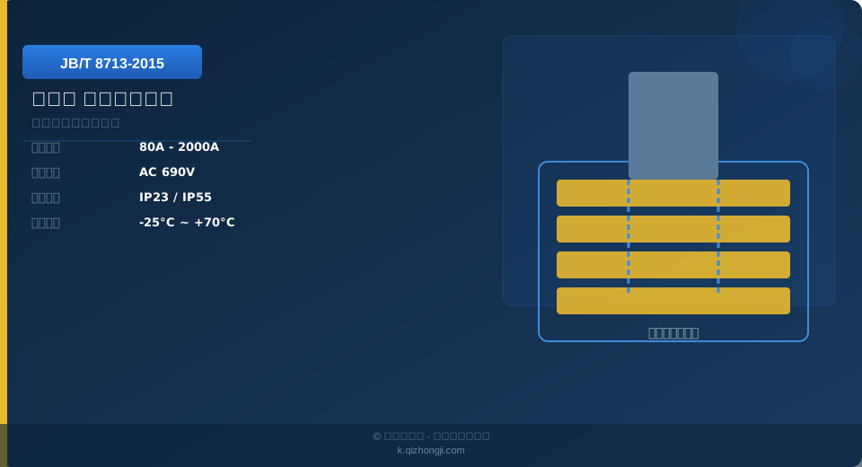
JB/T 8713-2015 Crane Safety Conductor Rail Standard Guide

JB/T 8713-2015, the product standard for enclosed conductor rails used on cranes, defines the classification, technical requirements, test methods, installation rules, and inspection rules for these systems. It applies to conductor rail systems that supply power to moving equipment such as bridge cranes, gantry cranes, and underslung cranes.

JB/T 8713-2015 is the product standard governing enclosed conductor rails for crane applications. It specifies the classification, technical requirements, test methods, and inspection rules for conductor rail systems that power bridge cranes, gantry cranes, and similar equipment. Enclosed conductor rails are the mainstream choice for modern crane power supply systems, offering a safe, reliable, and low-maintenance solution.

JB/T 9551


Conductor Rail Types and Construction

JB/T 8713-2015 classifies enclosed conductor rails by construction into three types: single-pole modular rails, where each conductor is individually insulated and can be flexibly combined into 3 to 16 poles with current ratings from 40 A to 500 A; multi-pole composite rails, where multiple conductors run in parallel within a single housing, offering 3 to 8 poles with current ratings from 20 A to 150 A in a compact design; and tubular conductor rails, where conductors are enclosed in an insulated tube with an IP65 protection rating, making them suitable for outdoor and dusty environments.

Core construction of conductor rails: the conductive elements use copper busbars (T2 copper, conductivity ≥97% IACS) or aluminum busbars (6063-T5 aluminum alloy, lighter in weight but with only 60% of copper's conductivity). The insulating housing is made of PVC or ABS engineering plastic (flame-retardant V0, operating temperature -20°C to +85°C). The current collector consists of carbon brushes, a brush holder, and a spring-loaded pressure mechanism.

Technical Requirements and Performance Parameters

Key performance parameters specified by the standard: rated current — available in 10 grades: 100 A, 200 A, 320 A, 400 A, 500 A, 630 A, 800 A, 1000 A, 1250 A, and 1600 A. Insulation resistance — between the conductor and the housing must be ≥10 MΩ (measured with a 500 V megohmmeter). Dielectric strength — the rail must withstand a 2500 V power-frequency dielectric test for 1 minute without breakdown or flashover.

Temperature rise limit — when continuously energized at rated current until thermal equilibrium is reached, the conductor temperature rise must not exceed 60 K (with an ambient temperature of 40°C, the conductor temperature stays at or below 100°C). The straightness deviation of the guide rail must be ≤3 mm per 2 m, with a cumulative deviation of ≤10 mm over the full length. The contact pressure of the current collector carbon brushes should be 15 to 25 N, with a pressure difference of ≤5 N between individual brushes.

Installation Requirements

Installation height of conductor rails: the lowest point must be at least 2.5 m above the floor in areas where personnel walk, or at least 2.0 m above maintenance walkways. Support brackets are typically spaced 1.5 to 2 m apart, with an additional bracket added on each side of every joint. Conductor rails can be installed in straight or curved runs — the bending radius must be ≥2 m for multi-pole rails and ≥1 m for single-pole rails.

Power feed points — for rail lengths up to 50 m, a single feed point at one end is sufficient; for lengths between 50 and 100 m, feed points are required at both ends; for lengths exceeding 100 m, multiple intermediate feed points should be provided. Expansion compensation — for rails 50 m or longer, expansion sections must be installed (with 10 to 20 mm of telescoping clearance) to accommodate thermal expansion and contraction of the rail due to temperature changes.

Inspection and Maintenance

Factory acceptance tests include visual inspection, insulation resistance testing (≥10 MΩ), and dimensional inspection. Type tests are conducted every three years and cover temperature rise testing, dielectric strength testing, aging resistance testing, and carbon brush life testing. Routine maintenance — inspect the rail surface for wear or burn marks and verify proper carbon brush contact on every shift.

Check joint temperature rise monthly using an infrared thermometer. Clean dust from the rail surface every three months. Replacement criteria: replace the rail when conductor wear exceeds 20% of the original cross-section, when the insulating housing is damaged and exposes the conductor, or when the rail is severely deformed and cannot be straightened. Carbon brushes should be replaced when worn to one-third of their original length.

Current Ratings

100–1600 A

Protection Rating

IP23–IP55

Carbon Brush Life

Wear ≤1 mm/1000 h

Contact Pressure

15–25 N

Insulation Resistance

≥10 MΩ

Operating Temperature

-20°C to +85°C

Kelude Heavy Industry: Engineered Lifting Solutions for Global Industry

Kelude Heavy Industry is a professional manufacturer dedicated to the design and production of industrial overhead cranes, gantry cranes, and electric hoists. With a strong focus on engineering excellence and manufacturing reliability, we deliver robust material handling equipment tailored to demanding industrial environments across the United States and Europe.

Comprehensive Crane Manufacturing Capabilities

Our manufacturing facility is equipped with advanced production lines and rigorous quality control systems. We specialize in a wide range of overhead traveling cranes, including single-girder and double-girder designs, as well as gantry cranes and specialized explosion-proof and low-headroom configurations. Every crane is engineered to meet international standards and is backed by our commitment to long-term performance and safety.

Product CategoryTypical Applications
Single-Girder Overhead CranesLight-to-medium duty workshops, maintenance bays, and assembly lines
Double-Girder Overhead CranesHeavy-duty production, steel mills, and large-scale fabrication
Gantry CranesOutdoor yards, container handling, and precast concrete plants
Electric Wire Rope HoistsPrecise load positioning and frequent lifting cycles

Key Features and Engineering Advantages

Our cranes are designed with performance and operator safety in mind. Key features include:

  • High-Strength Steel Structures: Optimized box-section girders provide excellent rigidity and reduced dead weight, minimizing building column loads.
  • Precision Travel Drives: Frequency-controlled motors and self-locking gearboxes ensure smooth acceleration, accurate positioning, and low maintenance.
  • Advanced Safety Systems: Features such as overload protection, anti-sway control, and emergency limit switches are integrated as standard or optional upgrades.
  • Low-Headroom Designs: Compact hoist and trolley configurations maximize effective lifting height, ideal for facilities with limited ceiling space.

Quality Assurance and International Standards

Kelude Heavy Industry operates under a strict quality management system. Our design, manufacturing, and testing processes align with internationally recognized standards, including ISO 4301 for crane classification and ISO 12480 for safe use. All equipment is thoroughly inspected and load-tested before shipment to ensure compliance and reliability.

Customized Solutions for Your Material Handling Needs

We understand that every facility has unique requirements. Our engineering team works closely with clients to provide customized crane solutions, including specific span lengths, lifting heights, and control systems. Whether you need a standard electric hoist or a complex multi-crane system, we deliver a solution that optimizes your workflow and enhances productivity.

Global Service and Support

With a growing presence in the US and European markets, Kelude Heavy Industry offers comprehensive after-sales support, including spare parts supply, remote diagnostics, and on-site maintenance services. Our goal is to ensure your crane operates at peak efficiency throughout its entire service life.

Contact Us for a Quote

Ready to enhance your material handling operations? Contact our sales team today to discuss your project requirements and receive a detailed quotation. We look forward to partnering with you.

Type Number of Poles Current Grade Application Environment
Single-Pole Modular 3~16Pole 40~500A Large Current, Multi-Trolley
Multi-Pole Composite 3~8Pole 20~150A Space-Constrained Applications
Enclosed Conductor (Tube Type)Conductor Rail / Busbar 3~8Pole 50~200A Outdoor Dusty Environment
Enclosed Conductor Rail 3~16Pole 100~1600A General-Purpose Applications

FAQ

Q: What are the main types of enclosed conductor rail systems?

A: Single-pole modular systems — each conductor is individually insulated, allowing flexible pole configurations from 3 to 16 poles with current ratings of 40–500 A. These are suitable for high-current applications and multi-collector setups. Multi-pole composite systems — multiple conductors run in parallel within a single housing, offering 3 to 8 poles with current ratings of 20–150 A and a compact structure. Tubular conductor rails — these provide a high protection rating (IP65) and are ideal for outdoor or dusty environments.

Q: What are the installation height and protection rating requirements for conductor rails?

A: Standard installation height requirements: the lowest point of the conductor rail must be at least 2.5 m above floor level in pedestrian areas, or at least 2.0 m where access is restricted to a maintenance walkway. For typical indoor environments, IP23 protection is sufficient; outdoor or dusty environments require IP55 and above. Conductor rail housings are typically made of PVC (V0 flame-retardant grade) or aluminum alloy.

Q: What is the replacement interval and what maintenance is required for current collectors (carbon brushes)?

A: Carbon brushes should be replaced when wear exceeds half of the original length — for example, a brush with an original length of 20 mm must be replaced once it wears down to 10 mm or less. Contact pressure should generally be maintained between 15 and 25 N. Inspection interval: check carbon brush wear and contact pressure every 2,000 operating hours or every 3 months, whichever comes first.

Q: What are the common faults encountered during conductor rail operation and how are they resolved?

A: Common causes include: excessive contact pressure (should be adjusted to 15–25 N) or insufficient pressure; rough conductor rail surfaces (which can be smoothed by sanding along the direction of travel with fine abrasive paper); poor straightness during installation; and excessive dust accumulation in the environment. Normal carbon brush wear should not exceed 1 mm per 1,000 hours of operation — if wear exceeds this rate, the root cause should be investigated.

Related News

contact

contact us

phone:
+86 13903802779

mail:3915269@qq.com

Working hours: Monday to Friday

Wechat
Wechat
SHARE
TOP