ISO 7752-1:2010 Crane Control Layout Standard Explained

ISO 7752-1:2010, "Cranes — Operator Controllers — Layout and Characteristics — Part 1: General Principles," is the governing standard for the arrangement of crane operator controllers. It defines the layout principles, direction consistency, controller type selection, and marking requirements for all crane types, serving as the ergonomic design baseline during the crane development phase.


Controller Layout Principles

ISO 7752-1:2010 establishes the following general principles for controller layout — Functional zoning: controllers are grouped by function (hoisting, traveling, slewing), with distinct separation between zones or a minimum spacing of 50 mm. Primary/secondary separation: main controllers (hoisting and luffing) are positioned within natural two-hand reach directly in front of the operator (≤500 mm from the operator), while auxiliary controllers (horn, lighting, Emergency Stop) are placed around the main controller cluster. Frequency of use: high-frequency controls (hoisting, Lowering) occupy the most accessible positions, while low-frequency controls (Outrigger deployment, jib extension/retraction) may be located further away.

Direction consistency: the operating direction of each controller must match the resulting motion of the controlled mechanism (see ISO 21455 for detailed requirements). Safety priority: the Emergency Stop Button and critical safety switches must be positioned for immediate access directly in front of the operator (red mushroom-head push button, diameter ≥25 mm). Ergonomic design: controller height should be within ±50 mm of the operator's seated elbow height; operating forces should be moderate (joystick 5–15 N, push button 3–8 N); and controller spacing must prevent inadvertent actuation (minimum 50 mm between adjacent controllers).


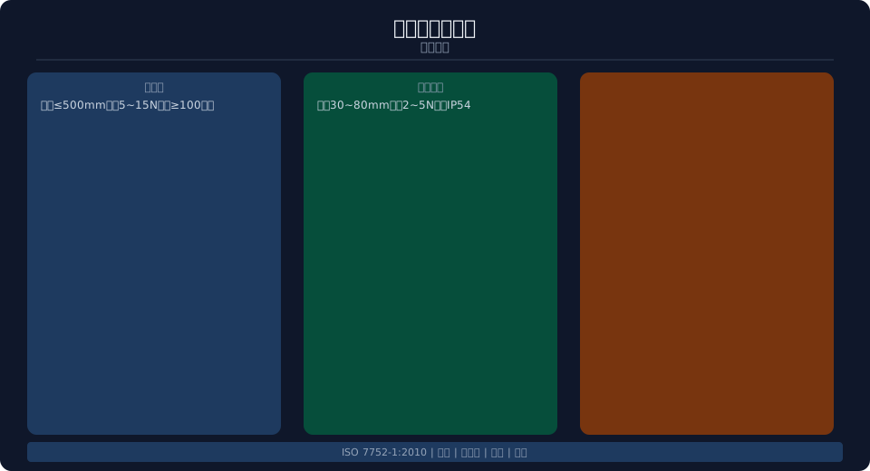
Standard interpretation diagram


Controller Types and Operating Characteristics

The standard classifies controllers by Operation Mode — Joystick type (single-axis or multi-axis, controlling 1 to 3 directions, recommended for combined motion operations), Push-button type (one button per direction, used for simple start/stop control), Cross-gate type (four-direction control panel with self-centering return), and Foot-pedal type (used for traveling speed control or Luffing Micro-motion). Operating characteristics by type — joysticks must feature automatic return-to-center (releasing the lever returns it to neutral), push buttons must provide tactile feedback (audible click on actuation) and visual indication (illuminated status light), and cross-gate controllers must include directional markings and a protective collar to prevent accidental actuation.

Key operating parameters — Button travel: joystick single-side stroke 30–80 mm, push-button travel 3–8 mm; Operating force: joystick 5–15 N, push button 3–8 N, foot pedal 10–30 N; Return force: joystick 2–5 N, push button 1–3 N. Protection Rating (IP): ≥IP54 inside the Operator Cabin, ≥IP65 for outdoor control stations. Electrical life: joystick switches ≥1,000,000 cycles, pb push button switches ≥500,000 cycles. All controllers must be marked with their function (graphical symbol or text) and an operating direction arrow; markings must be durable and remain legible after a 1,000-hour abrasion Test.

Main Controller Reach
≤500mm
Joystick Operating Force
5~15N
Push-Button Force
3~8N
Joystick Stroke
30~80mm
Push-Button Life
≥500,000 cycles
Joystick Life
≥1,000,000 cycles
Controller Type Degrees of Freedom operating force stroke application scenarios
Joystick Type(Single-Axis) 1Single-Axis 5~15N 30~80mm Hoisting / Lifting/Luffing
Joystick Type(Multi-Axis) 2~3Single-Axis 5~15N/Single-Axis 30~80mm combined motion
Pushbutton Type 1Direction 3~8N 3~8mm Start/Stop Control
Cross-Type 2Single-Axis 5~12N 10~20mm traveling Start/Stop Control
Foot Pedal Type 1Single-Axis 10~30N 20~50mm Travel Acceleration

Controller Marking & Layout

The standard specifies detailed requirements for the marking and layout of controllers. Each controller function must be identified by a label or graphical symbol in accordance with the ISO 7000 Graphical symbols standard. Markings shall be positioned above or in front of the controller, directly in the operator's line of sight, with a minimum character height of 5 mm for viewing distances up to 500 mm. The operating direction arrows on controllers must correspond to the actual movement direction of the machinery — upward for Hoisting, downward for Lowering, and left/right for Slewing or traveling in the respective direction.

When multiple controllers are arranged side by side, they must be grouped by function: Hoisting group (Hoisting/Lifting and Lowering), Luffing group (increasing/decreasing radius), Rotation group (left/right), and Traveling group (forward/reverse). Groups shall be visually separated by divider lines or color coding — green borders for hoisting functions and red borders for emergency operation. The control panel background should be dark gray or black to minimize glare and enhance marking legibility. The Inclination angle of the control panel should be perpendicular to the operator's line of sight for optimal visibility. Kelude's operator controller panels are engineered in accordance with ISO 7752-1:2010.


Safety & Emergency Operation

The standard sets forth requirements for emergency and safety controllers. The Emergency Stop Button must comply with ISO 13850 — red mushroom-head type with a minimum diameter of 25 mm, requiring a single press to cut off all power output and a twist-to-release action. The Emergency Stop Button shall be positioned within the operator's natural right-hand reach, no more than 300 mm away. A safety lock switch, operated by key, is required for maintenance mode to prevent accidental equipment startup. Emergency operation controllers (e.g., emergency Lowering, emergency release) must be identified with a yellow background and red text or symbols.

The standard also mandates fail-safe functionality for operator controllers in the event of Power Supply failure or control system failure — the controller must automatically return to the neutral position and the controlled mechanism must stop in its current position. The wireless remote control transmitter must be equipped with an active Emergency Stop Button that operates independently of the main control circuit, cutting off receiver Power Supply directly when pressed. Kelude crane controller systems provide comprehensive safety protection across all operating scenarios.

Controller Label Color operating force safety function
Hoisting / Lifting Joystick Handle Up/Down Green Zone 5~15N overloadautomatic stop
Slewing Joystick Handle Left/Right Blue Zone 5~15N limit switch Stop
Emergency Stop Button Red Mushroom Head Red Press≤30N Power Disconnect
Locking Switch Lock Icon Yellow Key Operated Anti-Accidental Start
Horn Button Horn Symbol Black 3~8N Audible and Visual Warning

FAQ

Q: What are the general principles for controller layout per ISO 7752-1:2010?

A: Functional grouping — controls are arranged by hoisting, traveling, and slewing functions. Primary/secondary separation — main controller is positioned within 500 mm of the operator. Frequency of use — high-frequency controls are placed in the most accessible positions. Directional consistency — control movement aligns with mechanism motion. Safety priority — the Emergency Stop Button is placed within immediate reach.

Q: What are the required operating forces for controllers?

A: Operating forces: joystick 5–15 N, push button 3–8 N, foot pedal 10–30 N. Stroke: joystick 30–80 mm, push button 3–8 mm. Minimum spacing between controllers is 50 mm to prevent accidental actuation. Reset force for joysticks is 2–5 N. Electrical life: joystick ≥1,000,000 cycles, push button ≥500,000 cycles.

Q: What are the marking requirements for controllers?

A: Each control must be identified by its function name or a graphical symbol per the ISO 7000 Graphical symbols standard. Label height must be at least 5 mm for viewing distances up to 500 mm, and labels must be placed on the top or front face. Operating direction arrows must correspond to the actual motion of the mechanism. Functional groups should be visually separated by divider lines or distinct color coding.

Q: What are the requirements for the Emergency Stop Button?

A: The Emergency Stop Button must be a red mushroom-head type with a minimum diameter of 25 mm. Pressing it cuts off all power output; releasing requires a twist action. It must be located within 300 mm of the operator's right hand. On wireless remote control transmitters, the emergency stop function must be independent of the main control circuit. Kelude cranes are equipped with Emergency Stop Buttons in both the Operator Cabin and on the Remote Control.

Related News

contact

contact us

phone:
+86 13903802779

mail:3915269@qq.com

Working hours: Monday to Friday

Wechat
Wechat
SHARE
TOP