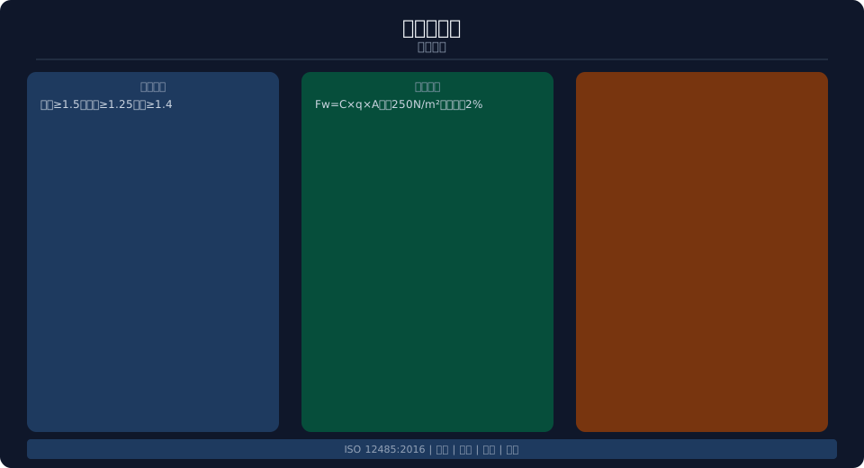
Tower Crane Stability Requirements per ISO 12485:2016
ISO 12485:2016, "Tower Cranes — Stability Requirements," is the dedicated standard governing anti-tipping stability for tower cranes. It specifies the stability requirements and verification methods for tower cranes under various operating conditions, including working, non-working, and erection/dismantling states.
Stability Verification Load Cases
ISO 12485:2016 mandates that stability verification for tower cranes cover the following load cases: working-condition stability (under rated load combined with wind load, verifying the crane's overall anti-tipping stability with a safety factor ≥1.5); non-working-condition stability (under extreme wind load — the maximum wind speed expected once in 50 years — with a safety factor ≥1.25, allowing for additional counterweight or anchoring); erection, dismantling, and climbing stability (under dynamic load combinations in these states, with a safety factor ≥1.4); and sudden load release stability (anti-backward-tipping stability when the suspended load is accidentally released during hoisting, with a safety factor ≥1.2).
Load combinations for each case include: dead weight G (tower mast, boom, balance arm, counterweight, and mechanism weights); suspended load L (rated lifting capacity × dynamic load factor of 1.1–1.3); wind load W (operation wind pressure at 250 N/m², non-working wind pressure based on the local once-in-50-years wind pressure); inertia load I (centrifugal force during slewing start/stop and braking inertia force); and inclination load T (foundation inclination calculated at 0.5°, with additional inclination for tied-in cranes due to deformation of the tie-in struts).
Anti-Tipping Verification Method
The standard specifies the moment method for anti-tipping verification — the ratio of the stabilizing moment (anti-tipping moment) Mst to the overturning moment Mov must not be less than the specified safety factor. The stabilizing moment includes: the moment of the crane's dead weight about the tipping line (excluding the suspended load), the moment of the counterweight about the tipping line, and additional stabilizing moments from anchoring or ballast. The overturning moment includes: the moment of the suspended load about the tipping line, the moment of wind load (including wind areas of the tower mast, boom, and suspended load) about the tipping line, and the moment of inertia force about the tipping line.
Determination of the tipping line: for fixed-base cranes, the tipping line is the centerline of the tower mast at the foundation edge; for traveling cranes, it is the contact line between the crane rail top surface and the crane wheels; for tied-in cranes, it is the centerline of the tower mast cross-section at the foundation. Each component of the stabilizing moment is multiplied by its respective stability factor (dead weight factor 0.9, counterweight factor 1.0, ballast factor 1.1), and each component of the overturning moment is multiplied by its respective overload coefficient (suspended load factor 1.3, wind load factor 1.0, inertia factor 1.2).
| verification load case | Load combination | Safety factor | control conditions |
|---|---|---|---|
| working condition | G+L+W+I+T | ≥1.5 | rated load+working wind |
| non-working condition | G+W+T | ≥1.25 | extreme wind+anchoring |
| erection and dismantling | G+W+T+dynamic | ≥1.4 | erection sequence Load |
| sudden unloading | G+unloading recoil | ≥1.2 | rearward stability |
| climbing condition | G+W+T+climbing Load | ≥1.4 | jacking stage |
Wind Load Calculation
The standard specifies detailed procedures for calculating wind load on tower cranes. The wind load formula is Fw = C × q × A, where C is the wind force coefficient (1.3–1.6 for the tower mast, 1.2–1.4 for the boom, 1.2 for the balance arm, and 1.0 for the suspended load), q is the wind pressure (250 N/m² in working condition; in non-working condition, the 50-year return extreme value is taken from local meteorological data), and A is the windward area (calculated from the actual profile of the tower mast and boom, multiplied by a fill factor of 0.4–0.6).
Wind pressure values corresponding to wind speed grades are as follows: Grade 6 wind (13.8 m/s) corresponds to 120 N/m², Grade 7 wind (17.1 m/s) to 180 N/m², and Grade 8 wind (20.7 m/s) to 270 N/m². The working-condition wind pressure for tower cranes is typically taken as 250 N/m² (equivalent to Grade 7–8 wind). For non-working conditions, wind pressure is calculated based on the local 50-year maximum wind speed, which can reach up to 1,500 N/m² in coastal areas. The calculation should also account for the non-uniform distribution of wind load along the tower height, with wind pressure increasing by 2% for every 10 m of additional height.
Stability Testing and Verification
The standard requires stability testing of tower cranes under the following conditions: during type approval of a newly designed crane (verifying theoretical stability through load testing), after tower height extension or retrofit (when structural parameter changes affect stability), after foundation settlement or inclination exceeds allowable limits (recalculating stability based on re-measured foundation conditions), and after incidents such as strong wind exposure or collisions (stability inspection). Stability testing employs strain gauges and inclinometers to monitor stress and deformation at critical points.
Kelude Heavy Industry tower cranes undergo full stability verification across all operating conditions in accordance with ISO 12485:2016. During the design phase, finite element analysis is used for anti-overturning calculations; prototype units are validated through load testing; and each factory-delivered crane comes with a stability verification report. If users modify the crane configuration during service—such as extending the boom or increasing the anchored height—a new stability verification must be performed.
| verification calculation Parameter | working condition | non-working condition | erection condition |
|---|---|---|---|
| Safety factor | ≥1.5 | ≥1.25 | ≥1.4 |
| wind pressure | 250N/m² | 50annual extreme value | 120N/m² |
| Load Coefficient | G0.9+L1.3+W1.0 | G0.9+W1.0 | G0.9+dynamic1.2 |
| inclination/tiltdegree | 0.5° | 0.5° | 0.5° |
FAQ: Tower Crane Stability Requirements & Wind Load Calculations
Q: What are the stability factor requirements for a tower crane in working condition?
A: In working condition (rated load + operation wind pressure of 250N/m² + foundation inclination of 0.5°), the anti-overturning stability factor must be ≥1.5. In non-working condition (extreme wind load + anchoring), the stability factor must be ≥1.25. During erection and dismantling, it must be ≥1.4. After sudden load release, the rear stability factor must be ≥1.2.
Q: How is wind load calculated?
A: Fw = C × q × A, where C is the wind force coefficient (tower mast: 1.3–1.6; boom: 1.2–1.4), q is the wind pressure (250N/m² in working condition; 50-year return extreme value in non-working condition), and A is the windward area multiplied by a fill factor of 0.4–0.6. Wind pressure increases by 2% for every 10m of height.
Q: How is the tipping axis determined?
A: For fixed-base cranes — the centerline of the tower mast at the foundation edge. For traveling cranes — the contact line of the crane wheels on the top surface of the crane rail. For tied-in cranes — the centerline of the tower mast cross-section at the foundation level. When calculating the stabilizing moment/overturning moment ratio, each component is multiplied by its corresponding coefficient.
Q: When is a stability re-evaluation required?
A: After extending the boom or changing the counterweight, when foundation settlement or inclination exceeds limits, when tie-in spacing is increased, after adding tie-in arms or retrofitting, or after exposure to strong winds or impact. Kelude offers stability re-verification calculation services for customers.