ISO 8686-5:2005 Load Combinations for Bridge Crane Design Explained

ISO 8686-5:2005 "Cranes — Design principles for loads and load combinations — Part 5: Overhead travelling cranes" is the governing standard for load combination design of bridge cranes. It defines load classification, characteristic values, and combination methods for the limit state design of overhead cranes.


Load Classification and Characteristic Values

Permanent loads G (dead weight of the crane bridge, trolley, and crane rail), variable loads Q (suspended load, wind load, and impact), and accidental loads A (earthquake and collision). The dynamic load factor ranges from 1.1 to 1.3 (higher values apply to heavy-duty service classes), and the impact allowance is 1.1 to 1.3. Bridge-crane-specific considerations include a wheel load eccentricity coefficient of 1.05 to 1.1 for the trolley, horizontal forces (15% of the crane bridge traction force, 10% of the trolley drive force, and 5% to 8% for suspended load sway).


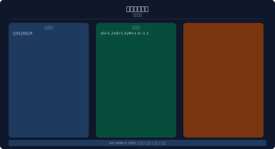
Load combination diagram for overhead bridge cranes


Load Combinations for Limit State Design

ULS Combination I: γG × G + γQ × Q (γG = 1.2, γQ = 1.5). ULS Combination II: basic loads plus wind load and rail misalignment, combined with a 0.9 reduction factor. SLS combination: G + Q using characteristic values, with deflection limited to L/400 to L/500. FLS combination applies the load spectrum factor. Critical sections to check include mid-span (maximum bending moment), the end sections (maximum shear force), and the quarter-span points.

Dynamic Load Factor
1.1–1.3
Impact Allowance
1.1–1.3
Rail Misalignment
1.05–1.1
Permanent Load Factor
γG = 1.2
Variable Load Factor
γQ = 1.5
Deflection Limit
L/400–L/500
Combination Load Itemized Verification
ULSⅠ G+Q γ G=1.2,γ Q=1.5 Strength/Stability
ULSⅡ G+Q+W+Rail Deviation ×0.9 Additional
SLS G+Qcharacteristic value Non-itemized Deflection/vibration
FLS Load spectrum Spectrum Coefficient Fatigue

Main Girder Structural Inspection

Camber is measured monthly (≥S/2000, with annual deflection ≤S/3000). Horizontal bow is checked quarterly (≤S/2000). Wave deformation is assessed semi-annually (≤3mm/m). Coating integrity is inspected annually (corrosion ≤5%). End carriage bolts undergo quarterly torque verification.

Inspection Period Method Standard
Camber Monthly Level Instrument ≥S/2000, Annual Deflection≤S/3000
Horizontal Bending Quarterly Tension Steel wire ≤S/2000
Waviness Deformation Semi-annual Straightedge ≤3mm/m
Coating / painting Yearly Visual Corrosion≤5%
End Carriage Bolt Quarterly torque wrench Per Specification

The permanent load (G) in the structural design of an overhead crane steel structure includes the dead weight of the main girder, end carriages, trolley, crane rail and its attachments, as well as electrical equipment (conductor rails, cables, etc.). The main girder's self-weight typically accounts for 40%–50% of the total permanent load, making it the dominant factor in structural design. The main girder weight can be controlled by optimizing the cross-section dimensions and the depth-to-span ratio — for box girders, the economical girder depth is generally 1/12 to 1/18 of the span (the ratio decreases as span increases), with the web spacing (box width) set at 0.4–0.5 times the girder depth. The trolley wheel loads are transmitted through the crane rail to the top flange plate of the main girder, and the local bending stress in the top flange must be managed by properly spacing the transverse stiffeners (at intervals ≤ 2 times the web height).

Although horizontal loads on an overhead crane are considerably smaller than vertical loads, they cannot be neglected in wide-span, large-tonnage cranes. The longitudinal horizontal inertia force generated during crane bridge starting and braking is calculated at 15% of the maximum traction force of the drive wheels (the number of drive wheels is determined by the total crane bridge weight and the friction coefficient between the wheels and the crane rail, typically taken as 0.12–0.15). The transverse horizontal inertia force from trolley starting and braking is taken as 10% of the trolley driving force. The horizontal force caused by the swing of the suspended load depends on the lifting height and the amplitude of load oscillation — when the lifting height is significant (>12 m), the load swing during hoisting and traveling can reach 0.5–1 m, and the resulting horizontal inertia force can be taken as 5%–8% of the suspended load. For outdoor overhead cranes, wind load must also be considered — the wind pressure acting on the side of the main girder is taken as 250 N/m² (working condition), with the wind-exposed area calculated as the projected side area of the main girder multiplied by a fill factor of 0.5 (0.4 for double-girder cranes exposed to wind as a combined unit).

FAQ

Q: Load classification?

A: Permanent (G), variable (Q), and accidental (A). Specific factors: eccentric rail coefficient 1.05–1.1, longitudinal horizontal force 15%, transverse horizontal force 10%, load swing 5%–8%.

Q: Load combinations?

A: ULS I (γG=1.2, γQ=1.5), ULS II (×0.9), SLS (no partial factors), FLS (spectrum coefficients).

Q: Critical sections?

A: Mid-span (maximum bending moment), ends (maximum shear force), and quarter-span points. Deflection ≤ L/400 to L/500, fundamental frequency ≥ 2 Hz.

Q: Main girder inspection?

A: Camber checked monthly, horizontal straightness quarterly, coating annually. Kelude overhead cranes are designed for all load combinations.

Related News

contact

contact us

phone:
+86 13903802779

mail:3915269@qq.com

Working hours: Monday to Friday

Wechat
Wechat
SHARE
TOP