CMAA 74 Single Girder Crane Specs: Key Requirements
CMAA 74 "Specifications for Electric Overhead Traveling Cranes" is a key technical specification in the crane industry. Developed by the Crane Manufacturers Association of America (CMAA), it is one of the most widely referenced standards for the design and manufacturing of EOT cranes in the United States. The standard systematically defines technical requirements for structural design, mechanism configuration, electrical systems, and safety devices of overhead cranes.
It provides design personnel, inspection bodies, and end users with a unified technical basis. Kelude strictly implements the requirements of this standard throughout its product development and manufacturing processes to ensure compliance and reliability.
Scope and Application of the Standard
CMAA 74 sets forth technical requirements and safety indicators for electric overhead traveling cranes, covering lifting appliances with a Rated Lifting Capacity above 0.5t. The standard applies not only to the design and manufacturing of new equipment but also provides clear technical guidance for inspection, maintenance, and modification of cranes already in service. As a key component of the crane standard system, it aligns with the EN 13001 Crane Safety Standard series and ISO 4309 Wire Rope Inspection Standard, forming a comprehensive framework of technical specifications. The defined technical parameters and Safety factor requirements give design personnel a clear design basis, while also offering quantifiable acceptance criteria for Type Test and Factory Acceptance Test conducted by third-party inspection bodies.

Core Technical Parameter Framework
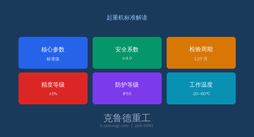
Under CMAA 74, the design and manufacturing of EOT cranes must satisfy a stringent set of technical parameters. These parameters are established on the basis of extensive test data and safety engineering principles, covering everything from material selection to structural design. The Safety factor ranges specified in the standard take full account of fatigue life and limit load conditions under severe operating environments. In engineering practice, design personnel select appropriate parameter combinations based on the crane's Work Duty / Classification, load spectrum, and service environment. The parameter cards below summarize the core technical indicators defined by the standard:
Key Parameter Comparison and Analysis
The comparison table below systematically contrasts the core parameters specified in CMAA 74 with general engineering practice. All values shown are taken from either mandatory or recommended clauses of the standard and should be strictly implemented during design and selection as well as Factory Acceptance Test.
| Item | technical requirements | Description |
|---|---|---|
| Work Duty / Classification | A1~A8According to Load spectrum+Number of cycles | A6or more shallfatigue calculation |
| design life | 20year(normalmaintenanceconditions) | According to Work Duty / Classificationequivalent number of cycles |
| Impact allowance | 1.1(A1~A5)/1.2(A6)/1.3(A7)/1.4(A8) | service impact+Hoisting / Liftingcombined impact |
| wheel load gaugecalculated | Maximum Wheel Loadas static Wheel load×Impact allowance | consideredelectric trolleyoff-center load+Crane Bridgenon-uniformity |
| fatigue designmethod | infinite life method(σmax<σe) | stress concentration Kt Coefficientdetail category |
| Wind Protection Device / Rail Clamp | outdoorcranewith Rail clamp | wind speed exceeding20m/sautomatic clamping Braking |
Inspection Requirements and Intervals
CMAA 74 Single girder cranes specification sets forth explicit requirements for factory acceptance tests, type tests, and periodic inspections of electric overhead cranes. Factory acceptance tests must be performed on each unit by the manufacturer's quality inspection department at the manufacturing facility, and equipment that passes inspection must be accompanied by a detailed inspection report and a certificate of conformity. The periodic inspection interval for cranes in service is determined by the work duty/classification and operating environment, and generally must not exceed 12 months.
| Item | technical requirements | Description |
|---|---|---|
| metal structure | main girder deflection/fatigue crack/Corrosion | annual+L/1000Deflectionlimit value |
| Crane wheeland Crane Rail | Tread surface Wear/Wheel flangethickness/rail straightness | quarterly+Wheel flange≥original thickness50% |
| Brake | Braking torque/Friction lining/Response time | monthly+Torque≥1.5times |
| safety device | Limit Switch/Overload Limiter/Buffer | all monthlyfunctional test |
Safe Operation and Management Requirements
Under CMAA 74, safe operation and routine management are critical to crane performance and longevity. The specification places strong emphasis on operator qualification and training, requiring that all operators complete specialized training and hold the appropriate certifications before operating the equipment. User units must establish a comprehensive equipment file management system that documents the full installation, use, maintenance and inspection history of each crane. Any safety hazard identified must be addressed through the rectification procedure specified in the standard, ensuring the equipment remains safe and controllable at all times. The standard also imposes operational restrictions for extreme operating conditions.
FAQ: CMAA 74 Work Duty, Impact Allowance & Wheel Load
Q: How does CMAA 74 classify crane service ratings?
A: The standard divides crane service ratings into eight classes, from A1 through A8, based on two criteria: load spectrum and total number of cycles. Load spectrum is categorized into four levels — Light (L), Medium (M), Heavy (H), and Severe (SH) — while total number of cycles is divided into ten ranges, N1 through N10. For example, a crane with a medium load spectrum and 100,000 cycles corresponds to class A4; a heavy load spectrum with more than 2,000,000 cycles corresponds to class A7 or A8. Classes A1 through A3 apply to cranes used for maintenance and occasional service, classes A4 through A6 cover general production cranes, and classes A7 through A8 are reserved for heavy-duty cranes in continuous operation. The service rating determines the structural fatigue design, mechanism configuration, and maintenance cycle requirements.
Q: What are the rules for selecting and applying the impact allowance?
A: The standard requires different impact allowance values depending on the service rating: classes A1 through A5 use 1.1, class A6 uses 1.2, class A7 uses 1.3, and class A8 uses 1.4. The impact allowance is applied in wheel load calculations and structural strength verification, combining both the traveling impact coefficient and the hoisting impact coefficient. Vertical impact caused by the crane bridge traveling over uneven runway rails, as well as the dynamic load generated when the load lifts off the ground, both increase the stresses on the structure. In practical design, additional factors must also be considered, including the skew load coefficient (uneven wheel load distribution caused by electric trolley positioning) and the horizontal inertia coefficient (horizontal forces during crane bridge acceleration and braking).
Q: What factors must be considered in wheel load calculations?
A: The standard requires wheel load calculations to use the maximum wheel load under rated load, taking into account: dead weight (main girder + end carriage + trolley + electrical equipment), rated lifting capacity, impact allowance (1.1 to 1.4), skew loading caused by the electric trolley positioned at the most unfavorable location, additional load from crane runway rail irregularities, and wind load (for outdoor installations). The maximum wheel load value is used for wheel block selection, rail selection, and the design of factory building support beams. The tread contact stress on the crane wheel must not exceed the allowable value for the material; for classes A7 through A8, the wheel tread hardness must reach HB350 or higher. Kelude uses the finite element method to precisely calculate wheel load distribution and optimize the wheel layout scheme.
Q: What are the fatigue design requirements under this standard?
A: The standard requires fatigue design calculations for all cranes rated class A6 and above. Fatigue design follows the infinite-life method, meaning structural members must not experience fatigue failure under an infinite number of load cycles at working stress levels. The design process involves classifying connection details to determine the stress concentration factor Kt, followed by mean stress correction using the Goodman diagram. Welded connections between the main girder flange and web plate are typically classified as Class C or Class D, with the corresponding fatigue limits obtained from S-N curves. The weld quality level must meet Grade B, and post-weld stress-relief annealing can improve fatigue life by approximately 20%. Fatigue details are carefully considered in the design of critical welded joints to ensure the product achieves a 20-year design life.
— Kelude specializes in crane design and manufacturing, with products built in full compliance with the CMAA 74 standard system. We provide lifecycle service covering solution design, manufacturing and installation, and after-sales maintenance. To learn how this standard is applied in our products, contact our technical team for detailed technical documentation.