

Interpretation of FEM 9.311 “Classification Standard for Structural Work Levels”
📌FEM 9.311 "Classification Standard for Organizational Levels"This is an important technical specification in the crane industry. Developed by the European Crane Manufacturers Association, this standard is specifically designed to determine the duty classes of various crane mechanisms (hoisting, travel, slewing, and boom extension). The standard classifies the duty classes of crane mechanisms into nine levels—V1 through V9—based on two parameters: the load spectrum factor and total operating time, thereby providing a basis for mechanism design, selection, and service life assessment.
This standard provides a unified technical basis for designers, inspection agencies, and users. Krude Heavy Industry strictly adheres to the technical requirements of this standard throughout the product development and manufacturing processes to ensure the equipment’s compliance and reliability.
Scope and Purpose of the Standard
FEM 9.311, “Classification Standard for Mechanism Duty Classes,” primarily specifies the technical requirements and safety criteria related to crane mechanism duty classes and applies to all types of lifting machinery with a rated lifting capacity of 0.5 metric tons or more. This standard not only covers the design and manufacture of new equipment but also provides clear technical guidance for the inspection, maintenance, and retrofitting of in-service equipment. As a key component of the crane standards system, this standard is harmonized with standards such as the EN 13001 series and ISO 4309, collectively forming a comprehensive system of technical specifications. The technical parameters and safety factor requirements specified in the standard provide designers with a clear basis for design and offer quantifiable criteria for type testing and factory acceptance testing by third-party inspection bodies.
Core Technical Specifications
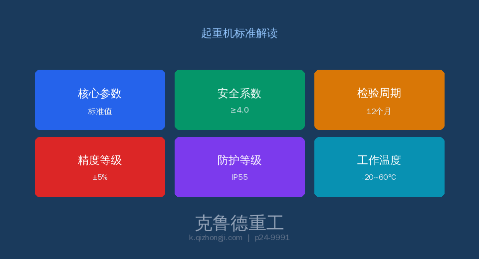
According to the technical specifications of FEM 9.311, the design and manufacture of machinery classified by service class must meet a series of stringent technical parameter requirements. These parameters are determined based on extensive experimental data and safety engineering theory, covering the entire process from material selection to structural design. The range of safety factors specified in the standard fully accounts for the fatigue life and ultimate load conditions of lifting machinery under severe operating conditions. In practical engineering applications, designers must select an appropriate combination of parameters based on factors such as the equipment’s working class, load conditions, and operating environment. The parameter cards below illustrate the core technical indicators of this standard:
Comparative Analysis of Key Technical Parameters
The following comparison table systematically contrasts the key parameters specified in FEM 9.311 with general engineering practice. The data in the table are values derived from mandatory or recommended provisions of the standard; it is recommended that these be strictly followed during design selection and factory inspection.
| Project | Technical Requirements | Note |
|---|---|---|
| Organizational Level | V1 (lightest) to V9 (heaviest) | Hoisting, travel, slewing, and boom extension are all different |
| Load Spectrum | L1: Mild / L2: Moderate / L3: Severe / L4: Very Severe | Distribution Characteristics of Lifting Loads |
| Total Working Hours | T0 (200 h)/T1 (400 h)/T2 (800 h)/ T3 (1,600 h)/T4 (3,200 h)/T5 (6,300 h)/T6 (12,500 h)/T7 (25,000 h)/T8 (50,000 h) | Within the 20-year design life |
| Hoisting Mechanism | General-Purpose V5–V6 / Heavy-Duty V7–V8 | V5 corresponds to A5–A6 |
| Operating Mechanism | General-Purpose V3–V4 / Heavy-Duty V5–V6 | Passenger car classification is 1–2 levels lower |
| Motor Duty Cycle | S3 (Intermittent)/S4 (Including startup effects) | Duty Cycle EC = 25% ~ 60% |
Inspection Requirements and Frequency
FEM 9.311 sets forth clear requirements for factory inspections, type testing, and periodic inspections of mechanisms classified by service level. Factory inspections shall be conducted unit by unit by the quality inspection department at the manufacturer’s facility; equipment that passes inspection shall be accompanied by a detailed inspection report and a certificate of conformity. The periodic inspection interval for in-service equipment is determined based on the operating class and operating environment, and generally shall not exceed 12 months.
| Project | Technical Requirements | Note |
|---|---|---|
| Load Spectrum Review | Statistical Analysis of Actual Load Records | Annual + vs. Design L |
| Work Hours Statistics | Operating Hours Counter or Counter | Year + Confirm T Grade |
| Functional Testing of Organs | No abnormal noise, temperature rise, or vibration | Monthly + Motor ≤ 100°C |
| Lifespan Assessment | Comparison of Actual Service Life vs. Design Life | Annual Assessment When the Service Life Reaches 801 TP3T |
Safety Operation and Management Requirements
Safety operations and daily management play a crucial role in the implementation of FEM 9.311. The standard places particular emphasis on the importance of operator qualifications and training, requiring that all operators undergo specialized training and obtain the appropriate qualifications before being allowed to work. Equipment-using entities should establish a comprehensive equipment record management system to document in detail the entire process of installation, use, maintenance, and inspection. Any identified safety hazards must be addressed in accordance with the corrective action procedures specified in the standard to ensure that the equipment remains in a safe and controlled condition at all times. In addition, the standard sets forth restrictive requirements regarding the use of equipment under extreme operating conditions.
Frequently Asked Questions
Q: How does FEM 9.311 determine the working level of a mechanism?
Answer: The duty class of a mechanism is determined by two parameters: the load spectrum (L1–L4) and the total operating time (T0–T8). The load spectrum reflects the distribution characteristics of the loads borne by the mechanism; L1 indicates frequent light loads and occasional full loads, while L4 indicates frequent full loads or overloads. Total operating time is calculated cumulatively over a 20-year design life. For example, a hoisting mechanism rated L3+T5 corresponds to V5. The rating of a hoisting mechanism is typically one level higher than that of the corresponding machine as a whole.
Q: Why do job levels vary across different organizations?
Answer: Different mechanisms on the same crane may have different duty classes: the hoisting mechanism has the highest duty class (directly bearing the load), the main girder travel mechanism has the next highest (frequent starting and braking), and the trolley travel mechanism has the lowest (short travel and light load). This differentiated design helps optimize manufacturing costs. For example, in an A5-class bridge crane, the hoisting mechanism is rated V5, the main girder travel mechanism is rated V4, and the trolley travel mechanism is rated V3; the corresponding motors are S4-40%, S3-25%, and S3-15%, respectively.
Q: What is the relationship between a motor’s duty cycle (EC) and its mechanical rating?
Answer: EC (Continuous Duty Cycle) refers to the percentage of total operating time during which the motor is energized. For V3-class mechanisms, EC=15% is commonly used; for V4–V5, EC=25%; for V6–V7, EC=40%; and for V8–V9, EC=60%. The higher the EC value, the greater the motor’s heat dissipation capacity and insulation class must be. The higher the mechanism class, the greater the requirements for motor power and the number of starts.
Q: Does the institutional level need to be reviewed during use?
Answer: When operating conditions change (e.g., the load spectrum changes from L2 to L3) or the frequency of use increases significantly (e.g., operating time changes from T5 to T6), the mechanism class must be re-evaluated. For upgraded mechanisms, it is necessary to verify whether the motor power, the reducer’s load-carrying capacity, and the brake’s braking torque meet the requirements of the new class. Krud Heavy Industry provides detailed calculation reports for the mechanism’s operating class upon product delivery.
🔧 — Specializing in crane design and manufacturing, our products strictly comply with the FEM 9.311 standard system. We provide full lifecycle services ranging from conceptual design, manufacturing, and installation to after-sales maintenance. If you would like to learn more about how this standard is specifically applied to our products, please contact our technical team to obtain detailed technical documentation.
