

Interpretation of the EN ISO 13849-1 Standard: "Safety-Related Parts of Control Systems for Machinery"
📌EN ISO 13849-1 "Safety-Related Parts of Control Systems for Machinery"This is an important technical specification in the crane industry. As a core standard in the field of mechanical safety concerning safety-related components of control systems, it introduces the concept of Performance Level (PL). The standard applies to electrical, hydraulic, and pneumatic safety control systems for cranes and corresponds to the SIL system defined in IEC 61508.
This standard provides a unified technical basis for designers, inspection agencies, and users. Krude Heavy Industry strictly adheres to the technical requirements of this standard throughout the product development and manufacturing processes to ensure the equipment’s compliance and reliability.
Scope and Purpose of the Standard
EN ISO 13849-1, “Safety-Related Parts of Control Systems for Machinery,” primarily specifies the technical requirements and safety criteria related to the safety control systems of cranes. It applies to all types of lifting machinery with a rated load capacity of 0.5 metric tons or more. This standard not only covers the design and manufacture of new equipment but also provides clear technical guidance for the inspection, maintenance, and retrofitting of in-service equipment. As a key component of the crane standards system, this standard is harmonized with the EN 13001 series, ISO 4309, and other standards, collectively forming a comprehensive system of technical specifications. The technical parameters and safety factor requirements specified in the standard provide designers with a clear basis for design and offer quantifiable criteria for type testing and factory acceptance inspections conducted by third-party inspection bodies.
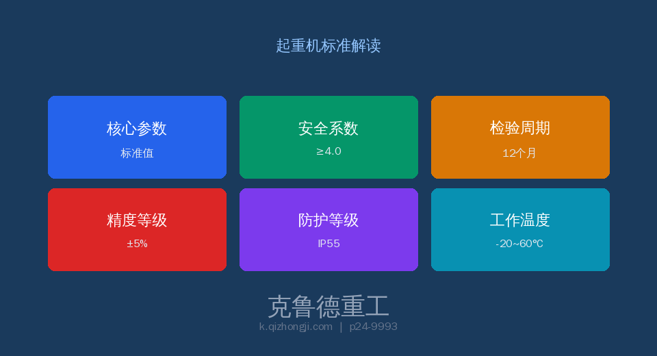
Core Technical Specifications
According to the technical specifications of EN ISO 13849-1, the design and manufacture of mechanical safety control systems must meet a series of stringent technical requirements. These parameters are determined based on extensive experimental data and safety engineering theory, covering the entire process from material selection to structural design. The range of safety factors specified in the standard fully accounts for the fatigue life and ultimate load conditions of lifting machinery under severe operating conditions. In practical engineering applications, designers must select appropriate parameter combinations based on factors such as the equipment’s duty class, load conditions, and operating environment. The parameter cards below illustrate the core technical indicators of this standard:
Comparative Analysis of Key Technical Parameters
The following comparison table systematically contrasts the core parameters specified in EN ISO 13849-1 with general engineering practices. The data in the table are values derived from the standard’s mandatory or recommended provisions, and it is recommended that they be strictly adhered to during design, selection, and factory acceptance testing.
| Project | Technical Requirements | Note |
|---|---|---|
| PL Level | PLd (Crane Safety-Related) | PLr = a (low) ~ e (high); d corresponds to SIL 2 |
| MTTFd (Component) | Low: 3–10 years / Medium: 10–30 years / High: ≥30 years | PLd requires a medium or high level |
| Diagnostic Coverage: DC | DC Off = 0% / Low = 60% / Medium = 90% / High = 99% | PLd requires DC ≥ Medium (90%) |
| Category CAT | CAT B/1/2/3/4 | PLd requires CAT3 (safe even with a single failure) |
| Redundant Architecture | 1002 Dual-Channel | Safety functions are not lost due to any single failure |
| CCF Precautions | ≥65 points (65-point grading scale) | Includes Isolation/Diversity/Conservation/Environment |
Inspection Requirements and Frequency
EN ISO 13849-1 sets forth clear requirements for factory inspections, type testing, and periodic inspections of mechanical safety control systems. Factory inspections shall be conducted unit by unit by the quality inspection department at the manufacturer’s facility; equipment that passes inspection shall be accompanied by a detailed inspection report and a certificate of conformity. The periodic inspection interval for equipment in service is determined based on the performance level and operating environment, and generally shall not exceed 12 months.
| Project | Technical Requirements | Note |
|---|---|---|
| PL Verification | MTTFd+DC+CAT+CCF Combined | Annual + Calculation Verification: PL ≥ PLr |
| Redundancy Testing | Channel-by-Channel Single-Fault Simulation | Monthly + Verification of Security Features Maintained |
| CCF Check | 65. Item-by-Item Review of the Allocation Table | Annual + ≥65 points |
| Emergency Stop Circuit | Forced Disconnection + Dual Channel | Monthly + Conductivity Test |
Safety Operation and Management Requirements
Safe operation and daily management play a crucial role in the implementation of EN ISO 13849-1. The standard places particular emphasis on the importance of operator qualifications and training, requiring that all operators undergo specialized training and obtain the appropriate qualifications before being allowed to work. Equipment-using organizations should establish a comprehensive equipment record management system to document in detail the entire process of installation, use, maintenance, and inspection. Any identified safety hazards must be addressed in accordance with the corrective action procedures specified in the standard to ensure that the equipment remains in a safe and controlled condition at all times. In addition, the standard sets forth restrictive requirements regarding the use of equipment under extreme operating conditions.
Frequently Asked Questions
Q: How do the PL levels in EN ISO 13849-1 correspond to the SIL levels in IEC 61508?
Answer: PLr=a corresponds to SIL 1 (None), PLr=b corresponds to SIL 1 (Low), PLr=c corresponds to SIL 1 (High), PLr=d corresponds to SIL 2, and PLr=e corresponds to SIL 3. The required performance level for crane safety control systems is PLr=d (corresponding to SIL 2). In practical applications, EN ISO 13849-1 provides a more intuitive method for selecting PL, while IEC 61508 provides a more detailed technical development process.
Q: What specific requirements does the PLd rating impose on MTTFd and DC?
Answer: PLd requirements: Mean Time to Dangerous Failure (MTTFd) for each channel ≥ 10 years (Medium), recommended ≥ 30 years (High); Diagnostic Coverage (DC) ≥ 90% (Medium); Category no lower than CAT3 (Single-Fault Redundancy); Common Cause Failure (CCF) Prevention Measures ≥ 65 points. All four parameters are mandatory, and the final PL is verified through calculations based on the system block diagram.
Q: What are the architectural characteristics of CAT3 (Category 3)?
Answer: CAT3 requires that the control system be able to continue performing safety functions after a single failure occurs, and that the failure must be detected. A typical architecture is a dual-channel (1oo2) configuration, in which each channel independently monitors the safety state, and the system enters a safe state whenever the output signals from either channel are inconsistent. The comparators between the two channels must provide sufficient diagnostic coverage. CAT4 further requires that the accumulation of faults will not result in the loss of safety functions.
Q: What are the measures to prevent common-mode failures?
Answer: CCF preventive measures are evaluated according to the 65-point scoring table: physical isolation (15 points), diversity design (20 points), protection (overvoltage/overtemperature/EMC) (10 points), environmental assessment (15 points), and component selection and data (5 points). A total score of ≥65 points is required to meet the PLd requirements. Typical measures include using sensors from different brands or based on different operating principles for the two channels, electrical isolation between channels, independent power supplies, and the partitioning of control cabinets.
🔧 Krude Heavy Industry — Specializing in crane design and manufacturing, our products strictly comply with the EN ISO 13849-1 standard system. We provide full lifecycle services ranging from conceptual design, manufacturing, and installation to after-sales maintenance. If you would like to learn more about how this standard is specifically applied in our products, please contact our technical team to obtain detailed technical documentation.
