

GB/T 22415-2008 Technical Specifications and Standards for Installation and Commissioning of Limit Switches for Crane Mechanisms
📌GB/T 22415-2008, “Cranes—Requirements for Mechanism Limit Switches,” is a specific standard for travel limit switches on cranes.This standard specifies the classification, technical requirements, operational accuracy, and test methods for limit switches in various mechanisms. It is a key safety standard for limiting the operating limits of crane mechanisms and preventing over-travel accidents.
GB/T 22415-2008, which is equivalent to ISO 12100-2:2003, is a standard specifically for limit switches in crane mechanisms. Limit switches serve as the first line of defense in a crane’s safety system—they automatically cut off the power supply when the hoisting mechanism reaches its limit position, preventing the crane from moving beyond the end of the track or lifting beyond the permitted height. This standard applies to the design, selection, and inspection of hoist height limiters, trolley travel limiters, luffing limiters, and slewing limiters for cranes.
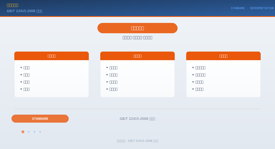
Classification and Technical Characteristics of Limit Switches
The standard classifies common limit switches used in cranes into four major categories based on their functions. Hoist Height Limit Switch—Activates when the hook rises to its limit position (where the upper surface of the hook block is at least 200 mm from the lower surface of the sheave block), cutting off power to the hoist circuit in the upward direction so that the hoisting mechanism can only descend and cannot ascend. Travel limit switches—Installed at both ends of the main and trolley travel tracks, these switches activate approximately 500 mm before the hoist reaches its limit position, cutting off power to the travel circuit and stopping the hoist. Boom Swing Limit Switch—Used on tower cranes and mobile cranes; it activates when the boom is swung to its maximum or minimum swing angle, cutting off power to the boom swing mechanism. Swing Limit Switch—Used on tower cranes; it activates when the swing angle exceeds the specified number of revolutions, cutting off power to the swing mechanism to prevent cable entanglement. Standards stipulate that each crane must be equipped with at least one limit switch for every direction of movement; for duty classes A6 and above, dual limit switches (mechanical + electronic) are recommended.
The technical specifications of the limit switch include: Operating Accuracy—The deviation in the trigger position during repeated operations should not exceed ±2% or ±10 mm (whichever is greater) from the set value. Actuation Speed—The total response time from the issuance of the over-limit signal to the opening of the main contactor shall not exceed 0.5 seconds. Environmental Adaptability—The limit switch shall operate reliably within a temperature range of -20 to +60°C and under conditions of 95% relative humidity. Protection Rating—Limit switches installed outdoors shall have a protection rating of at least IP65, and those installed indoors shall have a protection rating of at least IP54. Mechanical Life—The mechanical operating life of the limit switch shall be no less than 100,000 cycles. Electrical Life—Under rated voltage and current conditions, the electrical life shall be no less than 50,000 cycles.
Requirements for Limit Switch Installation and Commissioning
The standard specifies clear requirements for the installation location and adjustment accuracy of limit switches. The hoisting height limit switch should be installed at the end of the drum or along the wire rope winding path, and it should indirectly indicate the hook height by detecting the number of drum revolutions via a speed reducer or encoder. The trigger position of the limit switch should be set at a point no less than 200 mm from the upper limit of the hook (the minimum safe clearance between the hook block and the sheave block); the lower limit should ensure that there are still no fewer than three safety turns remaining on the drum when the hook is lowered to its lowest position. Travel limit switches for the main and auxiliary hoists should be installed at both ends of the track, with the trigger blocks secured to the end beams or main beams. The actuation position of the travel limit switches should be set at a distance of no less than 500 mm from the track end stop, allowing for sufficient braking distance.
When commissioning the limit switch, verify the actuation point by slowly moving the actual crane mechanism to its limit position. When commissioning the hoisting limit switch, first raise the hook slowly to near the limit position without a load. Observe the actual distance between the hook block and the sheave block when the limit switch activates, and adjust the trigger mechanism so that the distance is at least 200 mm. When commissioning the travel limit switch, move the hoist slowly to the end of the track, observe the actual distance between the end beam and the stop block when the limit switch activates, and adjust the position of the trigger block so that the distance is no less than 500 mm. After completing the commissioning of all limit switches, perform at least three repeat verification tests; the deviation at each actuation point must be within the allowable range. The commissioning record must include the limit switch model, set actuation position values, actual measured values, and the signature of the commissioning personnel.
Testing Methods and Routine Inspections
Inspection of limit switches includes factory inspection and on-site installation inspection. Factory inspection is conducted on a unit-by-unit basis: Visual inspection—the housing must be free of cracks, and markings must be clear; Operational inspection—manual contacts must operate smoothly and reliably without sticking; Insulation resistance test—the insulation resistance between live parts and the housing must be no less than 1 MΩ (measured with a 500 V megohmmeter). On-site installation inspections shall include: Verification of operating positions—confirm that the limit switch operates reliably at the set positions by running the mechanism at low speed; Reset check—after the limit switch operates, the mechanism should automatically or manually reset when running in the opposite direction; Interlock Function Verification—The circuits interrupted after the limit switch actuates must meet design requirements (the upward limit switch interrupts only the upward direction).
Routine inspections and maintenance are critical to the reliability of the limit switch. Before the start of each shift, visually inspect the limit switch for any external damage and check that the contact linkage is not jammed. Once a month, slowly operate the mechanism to its limit positions to verify that the limit switch functions properly (this can be done in conjunction with no-load operation). Quarterly, inspect the limit switch’s mounting bolts and contact wear, and remove any oxidation from the contact surfaces (silver contacts may be cleaned with alcohol; do not use sandpaper). Annually, check whether the limit switch’s actuation points have shifted due to mechanical wear or looseness; recalibrate as necessary and record the results in the equipment file. Krude Heavy Industry equips its cranes with high-quality limit switches as standard, and each unit undergoes individual actuation verification and interlock function testing before leaving the factory.
Limit Switch Types and Parameters Comparison Table
The following comparison table summarizes the technical specifications and inspection standards for various types of limit switches, to facilitate on-site reference and implementation by installation and inspection personnel.
| Limit Switch Types | Action Position | Accuracy Requirements | Inspection Frequency |
|---|---|---|---|
| Lifting Height Limit Switch | Upper limit of the hook ≥ 200 mm | ±10 mm | Monthly |
| Heavy-Duty Vehicle Travel Limiter | ≥500 mm from the stop block | ±50 mm | Monthly |
| Carriage Travel Limit Switch | ≥500 mm from the stop block | ±20 mm | Monthly |
| Amplitude Limiter | Maximum/Minimum Range | ±2% amplitude value | Every season |
| Rotary Limit Switch | Limited Number of Rotations | ±0.5 turns | Every season |
Common Limit Switch Faults and Troubleshooting
Limit switches may develop various malfunctions during prolonged use; timely troubleshooting and repair are crucial to ensuring the reliability of these safety devices. A common failure with hoist height limit switches is delayed or premature activation: Delayed activation is typically caused by gear wear in the reduction mechanism or a loose drive shaft; the gear meshing clearance in the reduction gearbox and the tightness of the coupling should be checked. Premature activation may result from a misaligned impact block or a reduction ratio error; the trigger position should be recalibrated. A common failure with travel limit switches is poor contact—oxidation or burnout of the contact surfaces can cause the circuit to be open or intermittent. The limit switch cover should be opened monthly to inspect the condition of the contacts; oxidation on silver contacts should be cleaned with anhydrous alcohol, and the contact assembly should be replaced in cases of severe burnout. Water ingress in outdoor limit switches is also a common cause of failure. Aging or failed O-rings can allow water to enter the interior, causing short circuits. O-rings should be replaced every two years, and during installation, ensure that the wiring port faces downward to prevent rainwater from flowing in along the cable.
Frequently Asked Questions
Q: What is the relationship between a limit stop and a buffer?
Answer: The limit switch serves as the first line of defense—it cuts off power to stop the mechanism before it reaches its limit position. The buffer serves as the second line of defense—it absorbs impact energy in the event that the limit switch fails. The two provide sequential protection; both are indispensable and cannot be substituted for one another.
Q: Can a limit switch be used as a normal stop switch?
Answer: No. Limit switches are safety devices designed to stop the equipment at its limit position in emergency situations; they should not be used as a means of stopping the equipment during normal operation. Frequent use will accelerate fatigue failure of the limit switches and reduce their safety and reliability.
Q: What are the risks associated with a failure of the hoisting height limit switch?
Answer: If the hoisting limit switch fails, the hook may continue to rise, causing the hook assembly to collide with the sheave assembly, resulting in the wire rope being overwound or even breaking, and the load falling. Therefore, the standard requires that the hoisting limit switch be inspected before the start of each shift.
Q: What does “dual configuration” mean in the context of a limit switch?
Answer: Dual configuration refers to the installation of two independent limit switches in the same direction of motion—the first set (working limit switch) operates normally, while the second set (safety limit switch) serves as a backup in the event of a failure in the first set. The two sets of limit switches should have independent power supplies, independent wiring, and independent triggering mechanisms, and should not depend on one another.
