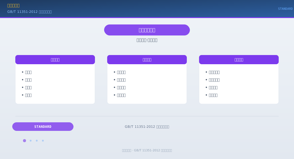
GB/T 11351-2012 Crane Wheel Tolerance Grades

GB/T 11351-2012 "Cranes — Wheels — Tolerances" is the dimensional tolerance standard for the manufacturing and inspection of crane wheels. The standard specifies manufacturing accuracy requirements for crane wheels, including diameter tolerance, geometrical tolerances, flange tolerances, and surface roughness. Used in conjunction with GB/T 11350, it is a key technical requirement for ensuring smooth crane operation and minimizing rail gnawing.

GB/T 11351-2012 is a dedicated standard covering manufacturing tolerances for crane wheels, setting out systematic technical requirements for dimensional tolerances, geometrical tolerances, and surface quality. Wheel manufacturing precision directly affects the crane's operating stability and service life. This article provides a detailed interpretation of the standard's core provisions.

GB/T 11351-2012 Crane Wheel Tolerance Standard


Standard Positioning and Tolerance System

GB/T 11351-2012 is the companion standard to GB/T 11350 "Cranes — Wheels," specifically governing the tolerance requirements for wheel manufacturing. Manufacturing precision directly influences the crane's operating stability, wheel service life, and rail wear conditions. Improper control of wheel diameter tolerance and geometrical tolerances can lead to: running skew and rail gnawing caused by diameter deviation between wheels, vertical bouncing of the crane caused by tread surface radial runout, lateral sway caused by end face radial runout, and derailment risk caused by wheel flange dimensional deviation. The standard specifies tolerance values according to the wheel diameter size range (Φ200~Φ1000mm).

Diameter Tolerance and Geometrical Tolerances

The main tolerance items specified in the standard: Wheel diameter tolerance — deviation of the nominal diameter D is executed to h9 grade (the larger the diameter, the greater the absolute tolerance value): at D=200mm the deviation is 0~-0.072mm, at D=500mm it is 0~-0.100mm, at D=800mm it is 0~-0.115mm. Tread surface radial runout — the radial runout of the tread surface relative to the axle bore during one full wheel rotation: ≤0.05mm for D≤500mm, ≤0.08mm for D>500mm. End face radial runout — the axial runout of the wheel flange end face relative to the axle bore: ≤0.10mm for D≤500mm, ≤0.15mm for D>500mm. Coaxiality of the wheel bearing bores Φ0.05mm (ensuring concentricity of the two bearing housings).

Diameter Tolerance
h9 grade D200:-0.072D800:-0.115mm
Tread Radial Runout
D≤500:≤0.05mm D>500:≤0.08mm
End Face Runout
D≤500:≤0.10mm D>500:≤0.15mm
Bearing Bore Coaxiality
Φ0.05mm Concentric bearings
Flange Thickness Deviation
±1mm Ensures alignment
Tread Roughness
Ra≤3.2μm Finish machined

Flange Tolerances and Assembly Requirements

The standard sets out specific dimensional tolerances for the wheel flange: flange width deviation ±1mm, flange height deviation ±0.5mm, and flange angle deviation on both inner and outer sides ±2°. The diameter difference between wheels on the same end carriage must not exceed 0.1mm, and the diameter difference across all wheels on the same crane bridge must not exceed 0.2mm. After assembly, the alignment difference between wheels on the same end carriage (the projected deviation of each wheel centerline on the horizontal plane) must not exceed 2mm. The vertical inclination of the wheel (the contact angle between the wheel tread and the rail) must not exceed 1/400 (approximately 0.14°). These assembly tolerance requirements are essential to ensuring smooth crane bridge and trolley travel without rail gnawing. After installation, a feeler gauge should be used to check the clearance between the wheel flange and the rail side: for double-flange wheels, the clearance on each side should be 5~10mm (uniform).


Crane Wheel Manufacturing Tolerance Comparison Table

The comparison table below lists the core parameter configurations for crane wheel manufacturing tolerances, for reference by those involved in wheel selection and usage.

Kelude Heavy Industry: Overhead & Gantry Crane Solutions

Kelude Heavy Industry specializes in the design and manufacture of heavy-duty overhead cranes, gantry cranes, and electric hoists. With a strong focus on engineering excellence and operational safety, our material handling equipment is built to deliver reliable performance across demanding industrial environments, from steel processing and shipbuilding to general manufacturing and logistics.

Frequently Asked Questions

Q: What is the lead time for a standard overhead crane?
A: Typical lead time for a standard single-girder crane is 4–6 weeks from order confirmation. Double-girder and custom-engineered cranes may require 8–12 weeks depending on complexity.

Q: Do you provide installation services overseas?
A: Yes, we offer turnkey installation services in most regions. Our technicians can supervise or fully handle the installation, commissioning, and load testing on site.

Q: Can your cranes be integrated with existing factory automation?
A: Absolutely. Our cranes can be equipped with Profibus, Profinet, or EtherNet/IP interfaces for seamless integration with PLC-based control systems. We also offer remote monitoring and diagnostic features.

Q: What safety certifications do your products hold?
A: All our cranes and hoists are CE-certified and comply with ISO 4301 for crane classification and IEC 60204-32 for electrical equipment. Explosion-proof models are ATEX and IECEx certified.

Q: What is your warranty policy?
A: We provide a standard 12-month warranty covering manufacturing defects and workmanship. Extended warranties and service contracts are available upon request.

Q: Can you provide spare parts for older crane models?
A: Yes, we maintain a comprehensive spare parts inventory for all our crane models, including legacy systems. Contact our support team with your crane serial number for quick identification.

Q: Do you offer financing options for large projects?
A: For major capital equipment purchases, we can arrange financing through our partner financial institutions. Please discuss your requirements with our sales team.

Q: How do you ensure crane safety during operation?
A: Our cranes are equipped with multiple safety layers: overload limiters, anti-collision systems, emergency stops, and redundant braking systems. We also provide operator training and safety audits as part of our after-sales service.

Q: What is the maximum span available for a gantry crane?
A: For double-leg gantry cranes, we can achieve spans up to 60m. For special applications, we have engineered custom solutions with spans exceeding 80m, subject to site conditions and load requirements.

Q: Can your cranes be used in extreme temperatures?
A: Yes, we offer cold-weather packages (down to -30°C) and high-temperature packages (up to +60°C) with appropriate material selection, lubrication, and electrical components.

← Scroll left / right to view full table →
Tolerance ItemTolerance GradePermissible Value(mm)inspection method
Wheel Diameter ToleranceIT7~IT8±0.05~±0.12Outer Diametermicrometer
Tread surface Radial RunoutIT8≤0.08~0.15dial indicator
Wheel flange Thickness ToleranceIT9±0.10~±0.25Caliper Measurement
Keyway SymmetryIT9≤0.05~0.12Special Inspection Gauge

Frequently Asked Questions

Q: What does h9 grade mean for wheel diameter tolerance? Why is the wheel diameter only allowed to have a negative deviation?
A: The h9 grade is a shaft-basis deviation class defined in the international tolerance standard ISO 286. The letter "h" indicates a fundamental deviation of zero (upper deviation = 0), while the number "9" denotes the tolerance grade (IT9). Therefore, h9 means the nominal wheel diameter is the maximum permissible diameter — the actual machined diameter can only be equal to or smaller than the nominal size, never larger. This is because if the wheel diameter exceeds the nominal size, the wheel would roll on the crane rail beyond the design wheel load range, causing abnormal wear on both the wheel and the rail. The lower deviation (minimum allowable size) is calculated as D × IT9/2, ensuring that the variation among individual wheel diameters remains within a controlled range.
Q: What are the consequences of excessive radial runout on the wheel tread?
A: Excessive radial runout on the tread surface (>0.08mm) means the tread is not concentric with the rotation center as the wheel turns—so for every full revolution, the contact point between the tread and the crane rail moves up and down once. This vertical oscillation leads to: 1) periodic vertical vibration (noticeable bouncing) during crane operation, compromising load stability and operator comfort; 2) a constantly varying contact area between the tread surface and the rail, creating uneven contact stress that accelerates localized tread wear; 3) alternating height differences between the two end carriages on the crane bridge, which in extreme cases can cause "three-legged" operation (one wheel briefly lifting off the rail). For these reasons, radial runout is one of the most critical geometrical tolerances in crane wheel manufacturing.
Q: How do you keep the alignment difference within tolerance during crane wheel installation?
A: Alignment difference is one of the most critical quality control indicators in overhead and gantry crane installation. Here's how to keep it in check: 1) Measure the diameter of each crane wheel before installation and pair wheels with similar diameters on the same side; 2) When assembling the End Carriage, use a laser alignment device or a taut steel wire (Φ0.5mm) to establish the centerline of each wheel, then adjust the Bearing Housing shims so all wheel centerlines fall on a single straight line; 3) After alignment, torque the Bearing Housing Bolts to spec and apply loosening prevention marks; 4) Once installation is complete, run the Crane Bridge at no-load and low speed to check for any signs of Rail gnawing (wheel flange rubbing against the Crane Rail). If any abnormality is detected, fine-tune the Bearing Housing position accordingly.
Q: How should wheel wear deviations beyond the standard be repaired?
A: The repair method for worn crane wheels depends on the type and extent of wear: 1) Uneven tread surface wear (excessive Radial Runout) — with the wheel still mounted, perform on-site Turning of the tread surface to restore accuracy to Ra≤3.2μm and Radial Runout ≤0.08mm; 2) Wheel flange wear (thickness reduction) — if the flange wear does not exceed 50% of the original thickness, the wheel may remain in service; beyond 50%, replacement is required; 3) Overall Wheel Diameter reduction due to wear (Diameter reduction exceeding 3% of the original diameter) — the wheel must be replaced entirely. Build-up welding is not recommended, as the heat-affected zone from welding destroys the surface Quenching structure, resulting in Lowering Wear Resistance. When replacing wheels, all wheels on the same End Carriage should be replaced simultaneously to ensure consistent Wheel Diameter across the carriage.

Related News

contact

contact us

phone:
+86 13903802779

mail:3915269@qq.com

Working hours: Monday to Friday

Wechat
Wechat
SHARE
TOP