

Equipping Cranes with “Black Boxes”—A Guide to Implementing CMS Condition Monitoring and Remote Operations and Maintenance
📋 The Crane CMS (Condition Monitoring System) achieves an upgrade in the O&M model from ”scheduled maintenance” to ”predictive maintenance” by deploying multi-source sensors—including vibration, temperature, and current sensors—in conjunction with edge computing gateways and 4G/5G cloud platforms. Vibration monitoring accuracy is ±0.1 mm/s RMS, and fault prediction accuracy is ≥92%.
With the continued advancement of Industry 4.0 and smart manufacturing strategies, the operation and maintenance model for lifting equipment is undergoing a profound shift from the traditional ”repair-when-broken” approach to data-driven ”predictive maintenance.” As a core piece of equipment in factory logistics, the cost of production interruptions caused by sudden crane downtime far exceeds the cost of equipment repairs themselves. The CMS Condition Monitoring System is equivalent to installing a ”black box” on a crane—it collects operational data from critical components around the clock and, through edge computing and cloud-based analysis, issues early warnings before failures occur, providing quantitative evidence to support maintenance decisions.
In its engineering practice in the field of intelligent cranes, Krude Heavy Industry has combinedGB/T 3811-2008 "Code for the Design of Cranes"In response to the need for safety monitoring of transmission mechanisms, CMS condition monitoring and remote operation and maintenance systems have been deployed at numerous manufacturing enterprises. This article systematically outlines the implementation process for CMS monitoring systems, covering everything from sensor selection and data acquisition architecture to cloud platform setup and fault prediction algorithms.
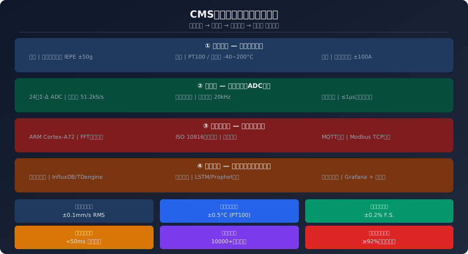
I. CMS System Architecture: A Four-Layer Framework from Sensors to the Cloud
A complete crane CMS condition monitoring system adopts a ”device-edge-cloud” collaborative architecture and is divided into four layers: the sensor layer, the data acquisition layer, the edge computing layer, and the cloud platform layer. The sensor layer is responsible for deploying various types of sensor components at key locations on the crane, including vibration accelerometers (IEPE type, range ±50g, frequency response 0.5 Hz–10 kHz), temperature sensors (PT100 platinum resistance, accuracy ±0.15 °C), Hall-effect current sensors (range ±100 A, linearity ≤0.11 TP3T), as well as auxiliary sensors for rotational speed, displacement, and other parameters. Sensor selection must balance interference immunity in industrial environments with long-term stability; all sensor components must have a protection rating of at least IP65.
The data acquisition layer uses a 24-bit Σ-Δ ADC for high-precision analog-to-digital conversion, with a sampling rate of 51.2 kS/s to cover the effective frequency range of the vibration signal, and features a built-in hardware anti-aliasing filter (cutoff frequency of 20 kHz). The multi-channel synchronous acquisition unit ensures that the time deviation between sensor channels does not exceed 1 μs, guaranteeing the time-alignment accuracy required for subsequent multi-source data fusion and analysis.
II. Vibration Monitoring: Selection of Accelerometers and the ISO 10816 Threshold System
Vibration monitoring is the most information-rich method for diagnosing faults in rotating machinery. In crane applications, vibration sensors are primarily deployed at three key measurement points: the motor drive-end bearing housing, the high-speed shaft bearing housing of the gearbox, and the drum support housing. For sensor selection, IEPE-type piezoelectric accelerometers (such as the PCB 352C33) are recommended, with a sensitivity of 100 mV/g, a measurement range of ±50 g, a frequency response of 0.5 Hz to 10 kHz, an operating temperature range of -54°C to 121°C, and support for ICP constant-current power supply. The preferred installation method is a rigid connection using M6 studs (which provides the flattest transfer function), followed by magnetic mounting; handheld probes should be avoided.
Vibration assessment follows the four-level threshold classification for Class I equipment (rotating machinery with a rated power of 15 kW to 300 kW) specified in the ISO 10816-3:2009 standard: Zone A ”Good” (≤1.8 mm/s RMS), Zone B ”Permissible” (1.8–4.5 mm/s RMS), Zone C ”Critical” (4.5–11.2 mm/s RMS), and Zone D ”Dangerous” (≥11.2 mm/s RMS). In engineering practice, Krude Heavy Industry has configured its CMS system to trigger a blue alert (monitor trend) when a crane’s critical rotating components enter Zone B, a yellow warning (schedule maintenance window) when they enter Zone C, and a red alarm (shut down immediately) when they enter Zone D.
III. Temperature and Current Monitoring: Multidimensional Health Assessment
Temperature serves as a ”thermometer” for the health of electromechanical equipment. The CMS system deploys PT100 platinum resistance temperature sensors at the ends of the motor’s three-phase windings, in the gearbox lubricant sump, and near the brake linings. Continuous monitoring of motor winding temperature can detect abnormal temperature rise trends 24 to 72 hours before bearing seizure (the rate of temperature rise typically increases sharply from the normal 0.5°C/h to 5–15°C/h). A continuous rise in gearbox oil temperature often indicates abnormal gear meshing or lubrication failure; alarm thresholds are set for oil temperatures exceeding ambient temperature plus 40°C or absolute temperatures exceeding 85°C. Monitoring the temperature of brake linings helps prevent thermal degradation of the friction material caused by prolonged brake drag.
Current monitoring provides a direct means of detecting electrical faults in motors. The CMS system installs Hall-effect current sensors in the motor’s main circuit to perform high-speed synchronous sampling (≥1 kS/s) of the three-phase currents, calculating three-phase imbalance, total harmonic distortion (THD), and RMS current trends in real time. An early warning is triggered when the three-phase current imbalance exceeds 5%; possible causes include inter-turn short circuits in the windings or unbalanced supply voltage. Furthermore, using MCSA (Motor Current Signature Analysis) technology, FFT spectral analysis is performed on the stator current to identify characteristic frequencies associated with rotor bar breaks ((1±2s)×f₀ sideband), air gap eccentricity, and bearing failures, thereby enabling early diagnosis of motor faults.
IV. Key Performance Indicators for CMS
V. 4G/5G+ Cloud Platform Architecture: Data Migration to the Cloud and Remote Operations and Maintenance
After completing local signal processing, the edge computing gateway uploads structured data to the cloud platform via a 4G/5G wireless network. MQTT (Message Queuing Telemetry Transport) is used as the primary uplink protocol. QoS Level 1 ensures that data is delivered at least once, and with a fixed header of only 2 bytes, it is well-suited for low-bandwidth industrial field environments. Downlink control commands utilize MQTT’s request/response mode to enable remote parameter configuration and OTA firmware updates. For legacy devices still using the Modbus RTU fieldbus, the edge gateway performs protocol adaptation by converting Modbus TCP to MQTT.
For cloud platform technology stacks, we recommend a combination of a time-series database (InfluxDB or TDengine), a message queue (EMQX or VerneMQ), and a visualization dashboard (Grafana). Time-series databases are specifically optimized for writing and compressing timestamped data, with single-node write throughput reaching up to one million points per second and a storage compression ratio of 10:1 to 20:1. The cloud platform implements a “Device Shadow” feature that caches the latest device status even when the device is offline and automatically synchronizes it once the connection is restored. The multi-tenant architecture supports permission isolation at the enterprise, workshop, and device levels, ensuring that monitoring data from different customers remains strictly independent.
VI. Fault Early Warning Algorithms: A Three-Stage Progression from Thresholds to Intelligence
CMS's fault early warning algorithm follows a three-tiered progressive strategy consisting of ”threshold alerts, trend forecasting, and machine learning-based anomaly detection”:
Level 1: Threshold Alert — Absolute thresholds are set based on physical principles and engineering experience. Examples include the four-level (A/B/C/D) classification boundaries for RMS vibration velocity in ISO 10816-3, motor winding temperature alarm thresholds (130°C for Class B insulation, 155°C for Class F insulation), and the 5% three-phase current imbalance ratio. The advantage of threshold-based alarms lies in their high response determinism and interpretability; the disadvantage is their inability to detect gradual trends and complex faults.
Level 2: Trend Forecasting — Using time-series analysis methods, the system performs linear regression slope analysis and moving average trend assessment on parameters such as vibration RMS value, temperature, and current. When the 7-day moving average slope of a parameter exceeds a preset threshold (e.g., daily temperature increase rate > 2°C/day), the system will issue a ”trend alert” even if the current value remains within the safe range.
Level 3: Machine Learning Anomaly Detection — Use unsupervised algorithms such as One-Class SVM or Isolation Forest to train a model on data from normal operating conditions, and flag data points that deviate from the normal operating envelope as anomalies. The model’s input features include the frequency-band energy distribution of the vibration spectrum, current harmonic components, temperature gradients, and other factors, totaling a 32-dimensional feature vector. The model is updated on a rolling 24-hour basis to account for the natural aging of the equipment.
| Monitoring Dimensions | Traditional Manual Inspections | CMS Online Monitoring |
|---|---|---|
| Test Frequency | 1 time per week to per month | Continuous Online (≥1 kS/s) |
| Vibration Detection | Using a handheld vibration meter, make a subjective assessment | Three-axis acceleration, automatic spectral analysis |
| Temperature Monitoring | Infrared Spot Thermometer, Single-Point Measurement | PT100 Continuous Data Acquisition and Trend Analysis |
| Current Analysis | Random Inspection of Clamp Meters | Continuous monitoring of three-phase current, MCSA diagnostics |
| Fault Alerts | “Fix it when it breaks” | Three-Tier Progressive Early Warning System (Threshold → Trend → ML) |
| Data Log | Paper records are easy to lose | Digital Storage, Cloud Backup |
▲ Comparison of Traditional Manual Inspections vs. CMS Online Monitoring
VII. Frequently Asked QuestionsQ: For which types of cranes is the CMS condition monitoring system suitable?
Answer: The CMS system is suitable for monitoring the drive mechanisms of various types of overhead and gantry cranes and electric hoists. It is particularly well-suited for critical workstation equipment such as metallurgical and foundry cranes that operate continuously 24 hours a day with a lifting capacity of 10 metric tons or more, as well as cranes used on continuous production lines where it is difficult to shut down operations for offline maintenance.
Q: How do the four threshold levels (A, B, C, and D) specified in the ISO 10816-3 standard for CMS vibration monitoring correspond to actual crane operation and maintenance decisions?
Answer: Zone A (≤1.8 mm/s RMS) indicates normal operating conditions; Zone B (1.8–4.5 mm/s) triggers a blue alert, requiring maintenance according to the scheduled cycle; Zone C (4.5–11.2 mm/s) triggers a yellow warning; a shutdown window for maintenance must be scheduled within 48 hours; Zone D (≥11.2 mm/s) triggers a red alarm; shut down immediately to investigate.
Q: In the CMS system’s 4G/5G communication solutions, what advantages does the MQTT protocol offer over Modbus TCP when it comes to uploading data to the cloud?
Answer: The MQTT protocol is based on a publish/subscribe model, with a message header of only 2 bytes, resulting in approximately 70% less bandwidth consumption than the Modbus TCP polling mode. It supports mechanisms such as QoS levels, Last Will messages, and Retained Messages, making it better suited for reliable transmission in environments with large-scale concurrent device connections and unstable network conditions.
Q: Approximately how long is the return on investment (ROI) period after deploying a CMS? In what areas are the main cost savings realized?
Answer: In a typical project, the payback period is 12 to 18 months. Cost savings are realized in three areas: a 60% to 80% reduction in unplanned downtime (avoiding losses from production interruptions), a 30%–50% reduction in spare parts inventory (shifting from ”scheduled replacement” to ”on-demand replacement”), and a 40%–60% reduction in maintenance labor hours (precise fault localization, reducing troubleshooting time).
Standard Reference: GB/T 3811-2008 "Code for the Design of Cranes" | GB/T 36468.1-2018 "Lifting Machinery—Inspection and Maintenance Procedures—Part 1: General Requirements" | GB/T 28264-2017 "Crane Machinery—Safety Monitoring and Management System" | ISO 10816-3:2009 "Mechanical Vibration—Measurement and Evaluation of Machine Vibration on Non-Rotating Parts—Part 3"
