

Crane Weighing System Calibration & Error Analysis
In modern material handling operations, the accuracy of crane weighing systems is a critical determinant of production safety and cost accounting. Industry statistics indicate that over 30% of overload accidents stem from inaccurate weighing equipment. For an overhead crane with a rated lifting capacity of 50 tons, a mere 3% weighing error creates a blind spot risk equivalent to 1.5 tons. This article provides an in-depth analysis of the working principles behind these systems, explores the underlying logic of how errors amplify over time, and details calibration specifications to help equipment managers establish a scientific maintenance framework.
Compliance is a non-negotiable red line during the design and inspection phases of lifting appliances. In the structural design stage, engineers must strictly adhere to the explicit requirements for hoisting mechanism safety factors and load combinations outlined in FEM 1.001. During routine special equipment inspections and operation management, compliance with TSG 51-2023 Crane Safety Technical Supervision Regulation is mandatory, specifically regarding the operating accuracy and interlock logic of overload protection devices. These two standards collectively form the technical foundation for weighing systems from R&D through to operation and maintenance.
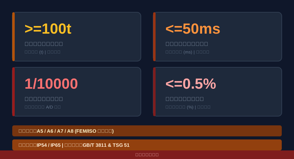
This guide begins with the sensor signal conversion mechanism, progressively delving into installation craftsmanship, error accumulation mechanisms, calibration procedures, and safety interlock strategies to comprehensively deconstruct the technical details and maintenance points of intelligent weighing systems.
Working Principles and Signal Transmission Mechanisms of Crane Weighing Sensors
The core sensing element of a crane weighing system is the resistance strain gauge sensor. Its basic principle relies on the minute deformation of an elastic body under force, which causes attached resistance strain gauges to undergo geometric changes, thereby altering their resistance value. When these strain gauges are configured as a Wheatstone bridge and subjected to excitation voltage, even slight resistance variations convert into millivolt-level voltage signals.
"According to industry measured data, the comprehensive non-linearity error of high-precision column sensors can be controlled within 0.02%, with a signal resolution typically reaching 1/10,000. This provides the physical basis for smart cranes to achieve precise load management."
To intuitively understand the signal conversion process, consider this engineering case study. Assume a column sensor with a rated load of 50t and a sensitivity specification of 2.0mV/V is used, with an instrument excitation voltage set at 10V. The theoretical output voltage calculation when the lifting spreader is at full load is as follows:
Full Load Output = Rated Load Ratio (100%) × Sensitivity (2.0mV/V) × Excitation Voltage (10V) = 20mV.
If the instrument's A/D converter has a resolution of 24 bits, the system can detect minuscule voltage changes, ensuring extremely high data resolution.
Several factors contribute to measurement drift:
1. Mechanical Wear: Long-term, high-frequency impact loads can cause irreversible plastic deformation in the sensor's elastic body, altering its force-response characteristics.
2. Sensor Zero Drift: Insulation aging or moisture ingress in internal strain gauges can shift the initial balance of the bridge, causing the display to read non-zero values under no-load conditions.
3. Ambient Temperature Interference: The elastic modulus of steel fluctuates with temperature. Without adequate temperature compensation circuits, ambientTemperature differential directly translates into weighing errors.
⚠️ Note
During signal transmission, shielded cables must be used with single-point grounding. Poor grounding allows electromagnetic interference generated by frequency inverters or high-power motors to couple into the millivolt-level signal cable, causing erratic fluctuations in weighing data.
On-Site Installation Craftsmanship and Stress Relief in Intelligent Weighing Systems
The final accuracy of a weighing system depends not only on the sensor's intrinsic performance but also on on-site installation quality. In the hoisting mechanism of a smart crane, sensors are typically mounted at the fixed pulley shaft end or the wire rope fixing point. Installation must ensure that the load application axis aligns strictly with the sensor's force axis to avoid lateral forces or bending moments.
When positioning sensors and adjusting mechanical connections, the anti-collision safety distance for long travel must also be considered to prevent extreme impact loads from acting directly on the weighing node. Mechanical installation gaps are typically maintained between 2~3mm; this range ensures the scale body floats freely while preventing excessive displacement. Connection bolts must be tightened to a torque of 120N·m to ensure node stiffness.
"Engineering practice demonstrates that using spherical washers or self-aligning bearings during installation can effectively absorb misalignment angles caused by main girder deflection or uneven crane rails, reducing lateral force interference by over 80%."
Stress relief is a critical step in the installation process. After the initial loading of a newly installed weighing system, microscopic fitting and settlement occur at mechanical connection points. Therefore, at least three full-load pre-compression cycles must be performed before formal calibration. This allows residual stress within the mechanical structure to fully release, ensuring the stability of subsequent calibration data.
💡 Tip
After installation,Must / Essential inspect for any obstructions or debris between the scale body and surrounding steel structures. Even minor friction of 0.5mm can be amplified during dynamic hoisting, causing significant sawtooth fluctuations in the weighing curve.
Cause Analysis of Error Accumulation and Long-Term Cost Assessment
Many equipment managers observe that crane weighing system errors tend to increase over years of use. This phenomenon is not accidental but results from the combined effects of material physical degradation and worsening mechanical environments. The Kelude technical team's long-term tracking reveals that error accumulation primarily manifests in two dimensions: zero drift and measuring range gain attenuation.
From a materials mechanics perspective, the sensor's elastic body undergoes minute creep under long-term alternating loads. This creep causes the stiffness coefficient of the elastic body to change slowly, resulting in a year-over-year decrease in deformation volume for the same weight. Additionally, the annual drift rate typically hovers around 0.5%. If calibration is not performed promptly, cumulative errors after five years may exceed safety thresholds.
📊 Comparison of Major Error Sources and Their Impact Levels in Weighing Systems
| Error / DeviationsourceClassification | Typical manifestation characteristics | Counterweight SystemAccuracyImpact ratio on the system | Reversibility assessment |
|---|---|---|---|
| MachinerystructureWearWith jamming / Binding | No-loadFailure to return to zero / Zeroing failure,Dynamic databouncing | Approximately / Approx. 40% | Partially reversible(Restorable after cleaning) |
| ElasticityBulk material creep | Measuring RangeSlow annual gain driftLowering | Approximately / Approx. 35% | Irreversible(Requires recalibration / Re-adjustmentCalibration) |
| Ambient TemperatureDrift | Data shift during diurnal or seasonal transitions | Approximately / Approx. 15% | Partially reversible(temperatureRestoration implies recovery) |
| Electrical signal interference | Occasional numerical spike or system hang | Approximately / Approx. 10% | Partially reversible(ImprovementGroundingEliminated thereafter) |
When evaluating total cost of ownership, the initial purchase price is only the starting point. A weighing system lacking periodic calibration incurs hidden costs that far exceed expectations. For instance, conservative weighing settings force a crane into light load operation, reducing utilization rates. Conversely, inaccurate readings can lead to occasional overload events, resulting in significant maintenance costs due to structural component fatigue.
"Industry data indicates that Metallurgical Cranes with strict annual calibration plans see their lifecycle maintenance cost drop by approximately 30% compared to maintenance-free models. Furthermore, structural rework rates caused by overload decrease by 45%."
⚠️ Note
Do not overlook downtime cost when calculating long-term expenses, particularly regarding Sensor replacement. For assembly line cranes in continuous production, it is recommended to stock spare parts for key sensor specifications to minimize MTTR (Mean Time To Repair) during unexpected failures.
Periodic Calibration Protocols and Dynamic Compensation for Weighing Systems
To counteract error accumulation, periodic calibration is essential for maintaining accuracy. The process involves two stages: static test weight calibration and dynamic real-object verification. Static calibration primarily validates sensor linearity and the indicator’s A/D conversion precision, while dynamic calibration assesses the system’s comprehensive response capability during Hoisting / Lifting operations.
Before static calibration, technicians typically perform flaw detection on the Main Girder, such as weld crack detection, to ensure the integrity of the load-bearing structure. This prevents structural deformation during calibration that could distort data. The calibration interval is generally set at 12 months, with verification points covering four critical nodes at 20%, 50%, 80%, and 100% of the Measuring Range to generate an accurate error compensation curve.
The following table provides a detailed comparison of the core differences in operational procedures and technical indicators between static and dynamic calibration for field engineers.
📊 Comparison of Parameters and Processes: Static vs. Dynamic Calibration
| CalibrationDimension | Execution conditions | CoreverificationIndicator | Qualified / Conformingacceptance criteria |
|---|---|---|---|
| StaticTest WeightCalibration | Lifting spreaderStationary,None / Absentwind loadElectrical signal interference | Linearity、Repeatability、Zero-return error | Each / EveryverificationPoint error ≤ 0.1% |
| Physical dynamic objectCalibration | Hoisting mechanismNormal variable-speed operation | dynamic response time、Filtering smoothness | Dynamic fluctuation range ≤ 1.5% |
In the realm of dynamic compensation, modern smart instruments incorporate digital filtering algorithms. By capturing acceleration data during hoisting operations, the system calculates and deducts the additional dynamic loads caused by suspended load inertia in real time. This technology ensures that cranes display weight values closely approximating true static weight even during acceleration or deceleration phases.
💡 Tip
A common pitfall during calibration is relying on a single-point full-scale calibration. This approach fails to correct sensor non-linearity errors. Always employ multi-point calibration methods to ensure uniform accuracy across the entire measuring range.
Overload Protection Logic & Smart Crane Safety Interlock Strategies
The weighing system serves not only as a measurement tool but also as a critical safety barrier for lifting appliances. Setting overload protection logic requires balancing operational continuity with strict safety standards. Typically, systems utilize two-tiered protection thresholds: a pre-alarm triggers at 90% of the Rated Lifting Capacity to alert the operator, while immediate circuit interruption occurs at 105%, restricting operations to lowering only.
In dynamic weighing scenarios, the system integrates AI anti-sway algorithms to filter out inertia interference from swinging loads, isolating the true static weight component. This fusion strategy effectively prevents false alarms caused by load oscillation, enhancing overall reliability. Furthermore, safety interlock circuits require relay response times of ≤50ms to ensure instantaneous power cutoff under extreme operating conditions.
"The TSG 51-2023 Crane Safety Technical Supervision Regulation explicitly mandates that the operating error of overload protection devices must not exceed ±5% of the set value. Devices must prevent automatic reset, ensuring that manual intervention confirms safety after every overload shutdown."
To validate interlock reliability, consider this braking distance calculation: Assuming a Long Travel Speed of 60 m/min (1 m/s) and an emergency braking deceleration of 0.5 m/s², the braking distance s = v²/(2a) = 1²/(2×0.5) = 1 meter. Within this short 1-meter distance, the weighing system must complete weight sampling, logical judgment, and signal output within 50ms. This imposes stringent requirements on sampling frequency and PLC scan cycles, underscoring Kelude Heavy Industry's emphasis on redundancy verification in intelligent crane control system design.
⚠️ Warning
Never bypass or shield the normally closed contacts of overload protection relays. Circumventing safety interlocks disables overload prevention, significantly increasing the risk of catastrophic failures such as main girder deformation or wire rope breakage.
FAQ
Q: What is the typical service life of a weighing sensor?
A: Under standard operating conditions, high-quality alloy steel sensors are designed for a fatigue life of up to 1 million loading cycles. With proper routine maintenance—avoiding overload shocks and severe corrosion—the physical service life typically reaches 5 to 8 years. We recommend annual verification to ensure internal strain gauges have not undergone irreversible plastic deformation.
Q: What is the estimated budget for replacing a smart weighing system?
A: Costs depend on lifting capacity, sensor quantity, and instrument sophistication. For a single-girder crane, basic analog systems are cost-effective, while intelligent systems with remote data transmission and sway compensation cost approximately 30% to 50% more. Specific equipment lists and final Quotation are subject to the actual contract; we recommend contacting Kelude Heavy Industry for a customized solution.
Q: How can we resolve increased weighing errors in High-Temperature Environment?
A: High temperatures reduce the elastic modulus of the sensor body and cause resistance drift in strain gauges. To address this, select high-temperature sensors equipped with temperature compensation circuits, keeping the temperature coefficient within 0.02%/℃. Additionally, enable dynamic temperature compensation algorithms in the instrument to correct zero-point and span drift caused by environmental temperature fluctuations.
Q: Which components require priority attention during routine maintenance?
A: Routine inspection should focus on checking the insulation layer of sensor cables for damage and verifying that gaskets in the Junction box are not aging or allowing water ingress. Regularly check mechanical limit switch gaps to ensure the scale body does not rub against surrounding structures, as mechanical interference is a common cause of erratic weighing data.
In summary, the precise operation of crane weighing systems relies on scientific selection, standardized installation, and strict Periodic Inspection. Facing complex operating condition challenges, Kelude Heavy Industry leverages deep technical expertise to provide comprehensive heavy-load customized solutions—from Sensor selection to smart instrument integration—helping enterprises achieve dual improvements in safety and efficiency.
