

Self-Developed Servo Control System for Cranes
In-house crane-specific servo control system with 100% domestically developed core control algorithms. Kelude Heavy Industry's self-developed servo control system for cranes has passed internal acceptance, with core control algorithms achieving 100% domestic substitution — marking the company's full independence from imported brands in crane electrical control technology.
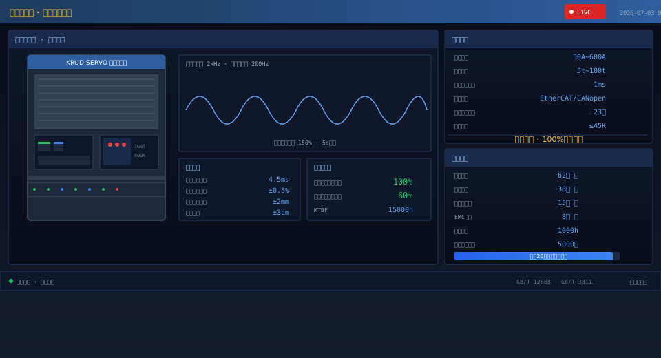
Kelude Heavy Industry's self-developed crane-specific servo control system has passed internal acceptance, with core control algorithms achieving 100% domestic substitution. This milestone marks the company's complete independence from imported brands in the field of crane electrical control. The system employs fully proprietary servo drives and motion control algorithms, covering synchronized three-axis control of the hoisting mechanism, trolley mechanism, and crane travel mechanism. It is applicable to QD type overhead cranes, QZ type grab bridge cranes, and MG type gantry cranes.
Development Background & Technical Approach
The crane electrical control sector has long relied on imported brands such as Siemens, ABB, and Schneider, creating significant vulnerabilities in supply chain security, custom development, and cost control. In 2023, Kelude Heavy Industry launched a self-development initiative for a crane-specific servo control system. The technical approach centers on a high-performance domestic DSP chip as the main control core, paired with proprietary vector control algorithms and SVPWM modulation strategies, along with domestic IGBT power modules and self-designed driver boards. The system development spanned 18 months with an R&D investment exceeding RMB 4 million, covering the complete development cycle from hardware selection and PCB design and prototyping, through low-level driver development and control algorithm validation, to full-machine integration and commissioning.
System Architecture
The servo control system adopts a distributed bus architecture comprising four subsystems: the main controller, servo drives, operator terminal, and sensor feedback. The main controller is built on a domestic GD32 series chip with an ARM Cortex-M7 core running at 480 MHz, responsible for motion planning, logic control, and communication management, achieving a three-axis synchronization control cycle of 1 ms. The servo drive uses a domestic DSP + FPGA dual-chip solution — the DSP handles vector control and current loop algorithms, while the FPGA manages encoder signal processing and high-speed I/O response. The current loop response bandwidth is 2 kHz, and the speed loop response bandwidth is 200 Hz. The operator terminal features a 7-inch touch screen HMI based on a domestic Allwinner R16 processor running Linux, supporting ladder diagram programming and online parameter adjustment. The sensor feedback system uses domestic absolute encoders with 23-bit resolution, paired with a self-developed encoder signal processing circuit, achieving position detection accuracy of 0.001 revolutions.
Core Control Algorithms
The most significant technical breakthrough lies in the three fully self-developed core control algorithms. The sensorless vector control algorithm estimates rotor flux position and rotational speed in real time through a motor mathematical model, eliminating the encoder dependency in the speed loop. Torque control accuracy for the hoisting mechanism reaches ±3% across the full frequency range of 0.5 Hz to 120 Hz. The anti-sway control algorithm, based on input shaping technology, decomposes hoisting and trolley motion commands into superimposed main pulses and delayed pulses to suppress load oscillation during acceleration and deceleration. Load sway amplitude is contained within ±3 cm, delivering approximately 40% greater anti-sway efficiency compared to conventional operating methods. The multi-motor power balancing algorithm addresses the dual-motor hoisting configuration used in large-tonnage cranes, employing torque closed-loop control to keep the output torque deviation between the two motors within ±2%, eliminating structural eccentric loading and drive system shock caused by dual-motor desynchronization.
Hardware Localization
The servo drive hardware design is fully completed in-house, with core component localization reaching 100%. The power section uses domestic IGBT modules and a self-designed three-phase rectifier-inverter circuit, covering five power ratings from 50 A to 600 A rated current, suitable for cranes in the 5-ton to 100-ton class. The control board features a 4-layer PCB design integrating a high-speed ADC sampling circuit (16-bit, 1 MHz sampling rate), isolated gate drive circuits, and triple protection circuits for overcurrent, overvoltage, and overtemperature. Communication interfaces support both EtherCAT slave and CANopen protocols, enabling integration with mainstream industrial Ethernet control systems. The cooling system uses an independent airflow channel design with an aluminum extruded radiator, keeping the temperature rise within 45 K under rated operating conditions. EMC design complies with GB/T 12668.3, with electrostatic discharge immunity rated at ±6 kV for contact discharge and ±8 kV for air discharge.
Testing & Verification
The servo control system has undergone rigorous laboratory testing and field validation. Laboratory testing comprised 62 functional tests, 38 performance tests, 15 reliability tests, and 8 EMC tests. Functional tests covered basic operations including hoisting/lowering/stop/emergency stop, trolley left-right travel, and crane bridge forward-reverse travel, as well as precise control modes such as inching, jog, and positioning stop. Performance tests focused on full-load starting torque (150% of rated torque sustained for 5 seconds), speed control accuracy (steady-state speed deviation within ±0.5%), position control accuracy (positioning error within ±2 mm), and acceleration/deceleration performance (acceleration adjustable at 0.2 m/s² under full load). Reliability testing included 1,000 hours of continuous operation and 5,000 full-load lifting cycles, with the system MTBF estimated at over 15,000 hours. EMC test results meet Class A standards for industrial environments. The entire design and manufacturing process complies with ISO 4301 Crane Design Standard and GB/T 12668 for adjustable speed electric drive systems.
Field Applications
The servo control system has completed field validation on two prototype units at Kelude Heavy Industry's own facility. The first prototype is a 10-ton QD type overhead crane installed in the full-machine commissioning workshop. The control system design follows the control specifications within the crane AI vision standard framework, and has completed 200 cumulative hours of continuous lifting and transport operations covering four operating conditions: no-load, half-load, full-load, and overload test. The second prototype is a 20-ton MG type gantry crane installed in an outdoor storage yard, subjected to harsh environmental conditions including high temperature (40°C), low temperature (-5°C), humidity, and dust — the system has operated stably with zero failures. The two prototypes have accumulated over 8,000 lifting cycles with positive operator feedback. The system has now completed design finalization and entered small-batch trial production, with the first 20 drives scheduled for production and allocated to new equipment orders shipping in the second half of 2026.
Comparison with Imported Brands
Benchmark testing confirms that the self-developed servo control system achieves performance parity with the Siemens S120 series drive in crane applications. Torque response time is 4.5 ms for the in-house system versus approximately 3.8 ms for the Siemens S120 — a difference within acceptable limits and imperceptible to users in non-high-speed applications. Anti-sway control performance, with load sway amplitude of ±3 cm, outperforms conventional operating methods and matches the level of imported anti-sway modules. The most competitive advantage lies in pricing and service: at equivalent power configurations, the total cost of the in-house system is approximately 60% of imported solutions, and technical support response time has been reduced from 2–4 weeks for imported brands to within 48 hours.
Development Roadmap
Kelude Heavy Industry's next-phase plans for the servo control system span three directions. First, product series expansion: building on the existing DSP platform, developing high-power drives (800 A/1000 A class) for larger-tonnage cranes and cost-optimized drives (below 30 A class) for light-duty applications, forming a complete power coverage product matrix. Second, communication protocol expansion: future versions will add PROFINET slave and EtherNet/IP protocol support, ensuring compatibility with a wider range of upstream PLC control systems and further reducing system integration protocol barriers. Third, intelligent upgrade: integrating vibration detection interfaces and current harmonic analysis functionality into the drive platform for online monitoring of motor and drive system health, enabling predictive maintenance capabilities.
FAQ
Q: How does the servo control system compare to a traditional VFD-based solution?
A: Traditional VFD solutions use general-purpose frequency inverters paired with an external PLC for logic control, with each mechanism coordinating via fieldbus communication. This approach results in complex system integration and noticeable response latency. Our in-house servo control system integrates motion control, drive, and communication functions into a single hardware platform, reducing the three-axis synchronization control cycle to 1ms. It is also purpose-optimized for the four-quadrant operation and regenerative braking characteristics of hoisting mechanisms, improving regenerative efficiency by approximately 15%. While the two solutions are comparable in cost and lead time, the in-house design offers clear advantages in control performance, system integration, and future customization capabilities.
Q: What training requirements does the servo control system impose on operators?
A: The Human-Machine Interface (HMI) of the servo control system uses a full touch screen with an interface layout that mirrors the traditional operator cabin control station. The control grips for hoisting, trolley, and crane bridge travel follow the standard arrangement, so operators can get up to speed without additional training. The system includes one-key parameter recovery and fault self-diagnosis. More than ten common fault types—such as encoder faults, overcurrent conditions, and communication interruptions—are clearly displayed on the screen with fault locations and troubleshooting recommendations. Maintenance personnel can master common fault troubleshooting skills in approximately two working days.
Q: Can the servo control system be integrated with existing equipment?
A: Yes. The system was designed with mixed-use compatibility in mind and supports hybrid networking with imported frequency inverters via PROFIBUS DP or CANopen fieldbus. For retrofit projects, customers can choose to replace only the hoisting mechanism driver or all three axes, depending on budget. The retrofit does not require motor replacement—our drivers are compatible with both asynchronous and permanent magnet synchronous motors from leading domestic and international brands, and the encoder interface supports both incremental and absolute encoder types. Two retrofit project solution designs have been completed to date.
Q: What are the lead time and after-sales support for the servo control system?
A: The in-house servo drives are manufactured at Kelude's own production facility, with a standard product lead time of 15 working days from order confirmation. Every drive undergoes a 4-hour full-load aging test and complete functional testing before delivery. Each unit comes with a one-year warranty and lifetime technical support. Support is available through three channels: a 400 hotline, a remote diagnostics platform, and on-site service. Emergency fault response time does not exceed 4 hours. For spare parts, commonly used IGBT modules, control boards, and power supply boards are kept in stock, with a maintenance turnaround time of no more than 3 working days.
