Crane Wheel and Rail Tolerances Explained: ISO 12488-1:2012 Guide

ISO 12488-1:2012 "Cranes — Tolerances for wheels and rails — Part 1: General" is the foundational standard governing tolerances for crane wheels and rails. It specifies diameter tolerances, tread profile, flange dimensions for crane wheels, as well as rail installation tolerances and inspection/measurement methods applicable to all types of rail-mounted cranes.


Wheel Tolerances and Dimensional Requirements

ISO 12488-1:2012 sets out detailed manufacturing tolerances and dimensional requirements for crane wheels. Wheel diameter is selected based on the rated wheel load, with a common range of Φ250–Φ1000 mm and a diameter tolerance of h9 grade — for example, a Φ500 mm wheel permits a diameter tolerance of 0 to 0.1 mm. Wheel tread width is determined by the rail type: QU70 rail requires a tread width of ≥80 mm, while QU100 requires ≥110 mm. Tread surface hardness must be ≥300 HB with a hardened layer depth of ≥5 mm to ensure adequate wear resistance. Wheel flange height must be ≥25 mm and flange thickness ≥20 mm. The total clearance between the wheel flange and the rail side is controlled within 15–25 mm — insufficient clearance leads to rail gnawing (wheel flange rubbing), while excessive clearance causes skewing during travel.


Wheel and rail tolerances


Rail Installation Tolerances

Key tolerances for rail installation — the allowable deviation for rail top elevation is ±5 mm, with adjacent height differences over any 10 m length limited to ≤3 mm. Straightness of the rail centerline: deviation ≤2 mm over any 10 m. Span tolerance between rails is ±5 mm, and the span difference between corresponding cross-sections of the two rails must not exceed 5 mm. For rail joints installed at ambient temperature, the joint gap is 1–2 mm, with an additional 0.5 mm reserved for thermal expansion for every 10°C rise in ambient temperature. Both vertical and lateral joint misalignment must be ≤0.5 mm, checked with a 300 mm straightedge. Rail clamps for fixing must be spaced at ≤600 mm intervals, or ≤500 mm for heavy-duty classifications, with a clearance of ≤1 mm between the clamp and the upper flange of the rail. At expansion joints, a transition guide rail of ≥200 mm in length must be provided to ensure smooth wheel passage.

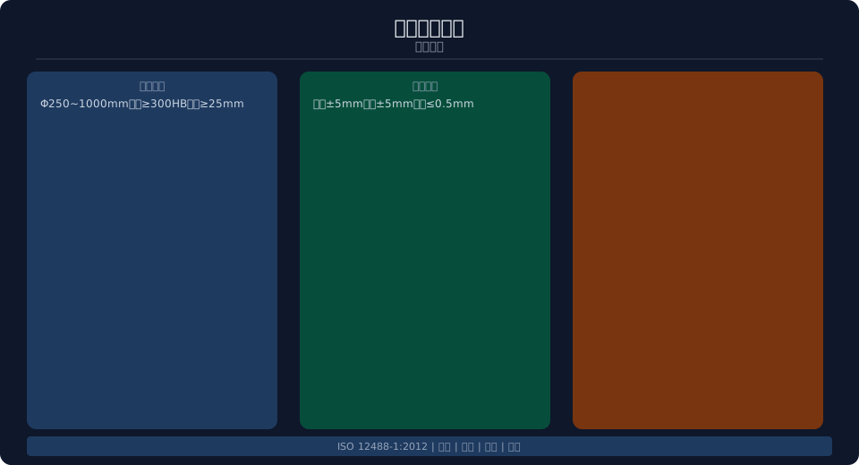
Wheel Diameter
Φ250–1000 mm
Tread Hardness
≥300 HB
Flange Height
≥25 mm
Rail Elevation
±5 mm
Span Tolerance
±5 mm
Joint Misalignment
≤0.5 mm
Tolerance Item Permissible Value measurement method applicable conditions
Wheel Diameter h9Grade Micrometer All Crane wheel
tread hardness ≥300HB Hardness Total hardened layer≥5mm
Wheel flange Clearance 15~25mm feeler gauge All Crane Rail
Rail Elevation ±5mm Level Instrument 10mInner≤3mm
Span ±5mm steel coil Micrometer Correspondingcross-section
joint gap 1~2mm feeler gauge Temperature Compensation

Inspection & Measurement Methods

For crane wheel inspection, the wheel diameter is measured at three points—the center and both ends of the tread surface—using an external micrometer, with the average deviation kept within the h9 tolerance grade. Tread surface hardness is checked with a Leeb hardness tester at three evenly spaced points around the tread circumference, requiring an average value of ≥300HB. Radial runout of the wheel is measured on a lathe using a dial indicator, with a maximum allowable deviation of ≤0.05mm.

For rail installation inspection, rail elevation is measured point-by-point from one end of the rail using a level instrument, with readings recorded every 2m. Rail straightness is verified by stretching a steel wire along the rail centerline under 200N tension and measuring the distance from the wire to the rail side face at 2m intervals. Span is measured with a steel tape at three locations—both ends and the midpoint of the rails.

Kelude Heavy Industry manufactures and inspects its crane wheels and rail systems in accordance with ISO 12488-1.

inspection items Instrument Method Standard
Wheel Diameter Micrometer Tread surface Average of Three Points h9Grade
tread hardness Leeb hardness tester Three-Point Uniform Distribution ≥300HB
radial runout dial indicator Lathe Measurement ≤0.05mm
Rail Elevation Level Instrument 2mSingle Point ±5mm(10m≤3mm)
rail straightness Steel wire+Caliper 2mSingle Point ≤2mm/10m
Span steel coil Micrometer Both Ends+Middle ±5mm

Crane Wheel & Rail Tolerance FAQs

Q: What are the wheel diameter tolerance requirements per ISO 12488-1:2012?

A: Wheel diameter is manufactured to h9 grade tolerance, with a Φ500mm wheel allowing 0 to 0.1mm deviation. Tread surface hardness is ≥300HB with a hardened layer of at least 5mm. Radial runout is held to ≤0.05mm. Flange height is ≥25mm, and the clearance between the wheel flange and rail is 15 to 25mm.

Q: What are the key tolerance values for rail installation?

A: Elevation tolerance is ±5mm (≤3mm within any 10m span), straightness is ≤2mm per 10m, and span tolerance is ±5mm. Joint gaps should be 1 to 2mm to allow for thermal expansion, with vertical and lateral misalignment at joints held to ≤0.5mm. Rail clamps must be spaced no more than 600mm apart.

Q: What problems can occur if the wheel flange clearance is too tight or too loose?

A: Insufficient clearance (below 15mm) causes severe friction between the wheel flange and the rail side — a condition known as flange rubbing or "rail gnawing" — which accelerates wear on both the wheel and the rail. Excessive clearance (above 25mm) allows the crane to skew during travel, resulting in a snaking motion that compromises positioning accuracy of the suspended load.

Q: What manufacturing standards does Kelude follow for crane wheels and rails?

A: Kelude manufactures crane wheels and rail systems to ISO 12488-1:2012. Wheel tread hardness is maintained at ≥300HB, and rail installation tolerances are strictly controlled within standard limits. All tolerance measurements are verified and documented before the equipment leaves the factory.

Related News

contact

contact us

phone:
+86 13903802779

mail:3915269@qq.com

Working hours: Monday to Friday

Wechat
Wechat
SHARE
TOP