

Passive vs Active vs Constant Tension Wave Compensation
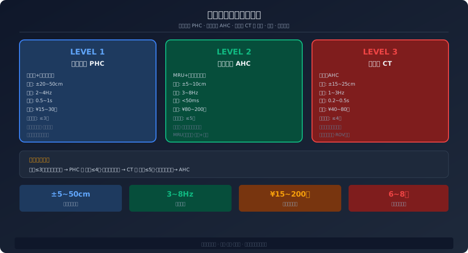
Offshore crane wave compensation systems fall into three tiers: passive heave compensation (PHC), active heave compensation (AHC), and constant tension (CT). Compensation accuracy improves progressively from ±20–50 cm for PHC to ±5–10 cm for AHC. System selection should weigh sea-state conditions, positioning accuracy requirements, and project budget.
In offshore lifting operations, the biggest variable is not the load weight—it is the constant motion of the platform beneath your feet. Wave-induced vessel heave can reach ±1.5–2.5 m in moderate sea states, with periods of 5–12 seconds. Without compensation, the hook rises and falls with the vessel, slowing productivity at best and causing serious accidents at worst, such as loads slamming into the deck or subsea equipment.
The technical parameter comparison across the three wave compensation tiers is based on the dynamic load factor calculation method in ISO 4301, with accuracy grading referenced against DNV-ST-0378 performance requirements for offshore crane wave compensation.
After nearly four decades of development, wave compensation technology has matured into a three-tier system: Passive Heave Compensation (PHC), Active Heave Compensation (AHC), and Constant Tension (CT). Each tier serves different application scenarios, offers distinct compensation accuracy, and carries its own cost range. Choosing the right one requires balancing marine environment, operational precision, and project budget.
Passive Heave Compensation: Accumulator and Cylinder Gas Spring Principle
Passive heave compensation (PHC) is the most fundamental and reliable approach. It works much like a giant gas spring—an accumulator and compensation cylinder are connected in series along the hoisting wire rope path. As the vessel rises (wire rope slackens), compressed gas in the accumulator pushes the cylinder to retract the excess cable. As the vessel falls (wire rope tightens), the cable pulls the cylinder, forcing hydraulic oil into the accumulator. The entire process is fully passive—no electronic control, no additional power consumption.
PHC accuracy is limited by the physics of gas compression—nitrogen pressure in the accumulator varies with volume (approximately adiabatic, PV^γ = constant)—so the compensation force changes nonlinearly with displacement. Typical PHC systems achieve ±20–50 cm accuracy in sea states of Hs = 2–3 m. Key advantages of PHC include: zero energy consumption, no electronic components (suitable for ATEX Zone 1 explosion-proof areas), and minimal maintenance—only periodic checks of nitrogen pressure and cylinder sealing. Typical applications: supply transfer, jacket installation assistance, and low-accuracy subsea equipment deployment.
Key design parameters for PHC systems include: total accumulator volume (typically 200–800 L, depending on compensation stroke and load), nitrogen precharge pressure (usually 80–90% of the system's minimum working pressure), compensation cylinder stroke (must be ≥1.5 times the maximum expected heave displacement), and piston rod diameter (checked against Euler buckling stability with a safety factor ≥3.5).
Active Heave Compensation: MRU and Servo Winch Closed-Loop Control
Active heave compensation (AHC) is currently the most widely adopted solution for offshore cranes. Unlike PHC, AHC is a closed-loop control system: an MRU (Motion Reference Unit) detects vessel heave acceleration and angle at a 200–500 Hz sampling rate. After Kalman filtering and double integration, real-time heave displacement is derived. The control system then issues speed commands to the winch servo motor—reeling in faster as the vessel rises, paying out faster as it falls—keeping the hook absolutely stationary in the inertial reference frame.
AHC accuracy is significantly better than PHC: ±5–10 cm in sea states up to Hs = 3 m, and ±15–25 cm in sea states up to Hs = 5 m. This level of precision is sufficient for demanding operations such as subsea Christmas tree installation, ROV launch and recovery, and wind turbine blade mating. The control algorithm is the core differentiator—beyond basic PID control, it typically includes feedforward control (acting in advance based on wave prediction), dead-band compensation (eliminating nonlinearity from spool overlap), and adaptive gain scheduling (adjusting controller parameters based on load changes).
AHC hardware is considerably more complex than PHC. The main added cost items include: MRU sensors (unit price ¥80,000–200,000, e.g., Kongsberg MRU-5 or SBG Ellipse-N), high-performance servo or proportional valves (frequency response ≥30 Hz, ¥30,000–80,000 each), PLC controllers (must support scan cycles below 2 ms, e.g., B&R X20 or Beckhoff CX series), and winch motor dynamic performance (speed response bandwidth ≥5 Hz, typically requiring bent-axis axial piston motors rather than radial piston motors).
Constant Tension: A Simplified AHC Alternative
Constant tension (CT) control can be viewed as a simplified version of AHC—it does not aim for absolute hook position stability, but instead regulates winch torque to maintain a constant preset tension in the wire rope. When the vessel rises and tension drops, the winch automatically hauls in; when the vessel falls and tension rises, the winch pays out. The CT control loop bandwidth is typically lower than AHC (approximately 0.5–2 Hz vs. 3–8 Hz), with compensation accuracy in the ±15–40 cm range.
The main advantages of CT are lower cost (roughly 30–50% of an AHC system) and simpler commissioning—no MRU required, only a tension sensor on the fixed end of the wire rope. Typical applications include: underway replenishment (UNREP), anchor chain deployment and recovery, and salvage operations. CT is not suitable for subsea equipment installation requiring precise positioning.
Comparing the Three Compensation Tiers
| Comparison Parameter | passive compensation PHC | constant tension CT | active compensation AHC |
|---|---|---|---|
| Operating Principle | Accumulator+Cylinder gas spring | tension sensor+winch Torque | MRU+servo winch Closed-loop |
| compensation accuracy | ±20~50cm | ±15~40cm | ±5~10cm (Hs≤3m) |
| Response Bandwidth | Machinery Inherent Frequency 0.3~0.8Hz | 0.5~2Hz | 3~8Hz |
| Applicable Sea State | Hs≤2m | Hs≤3m | Hs≤5m |
| Hardware Cost Coefficient | 1× (Baseline) | 0.3~0.5× | 2.5~4× |
| Energy Consumption | Zero(Fully Passive) | Extremely Low(Fine Adjustment Torque) | Moderate(servo winch) |
| Maintenance Complexity | Minimal(Air-only/Oil Inspection) | Extremely Low(tension sensor Calibration) | High(MRU+Servo Valve+PLC) |
| Typical Application Scenario | Recommended Solution | Sea State Threshold | Accuracy Requirement |
|---|---|---|---|
| Supplies/Provisions Transfer | PHCor CT | Hs≤2.5m | ±30cm |
| jacket/Pile Foundation Installation Assistance | PHC+AHCCombination | Hs≤2m | ±15cm |
| ROV/AUVDeployment/Retrieval | AHC (Essential) | Hs≤4m | ±10cm |
| Subsea Christmas tree/Manifold Installation | AHC (Essential) | Hs≤2.5m | ±5cm |
| Offshore Wind Turbine Blade Mating | AHC (Essential) | Hs≤2m | ±5cm |
| UNREPOffshore Replenishment | CT | Hs≤3m | ±25cm |
How to Choose a Wave Compensation System: A Decision Tree
① Start with sea conditions — The average annual significant wave height (Hs) at the operating site is the deciding factor. For Hs ≤ 2 m with accuracy requirements of ±30 cm or less, PHC is the preferred choice (lowest cost, zero energy consumption). For Hs between 2 m and 3 m, select CT or AHC. For Hs > 3 m, AHC is mandatory.
② Then consider the operation type — Subsea equipment installation (ROV, Christmas tree, wind turbine blades) calls for AHC under all sea conditions, because a 10 cm positioning deviation can prevent flange bolts from aligning. For supply transfer and salvage operations, CT provides sufficient performance.
③ Finally, weigh the budget — An AHC system adds approximately ¥500,000–1,200,000 (about $74,000–$177,000) in hardware costs, including the MRU, servo valve manifold, controller upgrade, and commissioning. If the project operates only in mild sea states with moderate accuracy demands, the savings from PHC or CT can be substantial.
Wave Compensation in Offshore Wind Installation: A Case Study
Offshore wind power is currently the strongest driver of wave compensation technology advancement. In a monopile installation project at a Chinese offshore wind farm, the installation vessel was equipped with an 800 t main crane and an AHC system. Operating in the East China Sea (average annual Hs = 1.8 m, maximum Hs = 4.5 m), the vessel handled monopiles measuring 7.5 m in diameter, 85 m in length, and weighing 1,200 t each. The AHC system played a critical role in two phases. First, during pile lifting — when the crane lifted the monopile from the transport barge, the relative heave motion between the two vessels (caused by wave phase differences, reaching 2–3 m) would, without AHC compensation, generate an impact load of 1.5–2 times the rated load at the moment the pile left the barge, potentially overloading the crane structure. The AHC system controlled the impact load to within 1.1 times the rated load by continuously adjusting the winch rope speed (peak speed 1.8 m/s). Second, during pile penetration and positioning — after the pile touched the seabed, verticality had to be maintained (tilt < 0.5°). The AHC system switched to constant-tension mode, setting the wire rope tension at 15%–20% of the pile weight (as a guiding force rather than a holding force). Simultaneously, the system worked with inclinometers on the pile in a closed loop to fine-tune winch movements (±5 cm accuracy), ensuring the pile stayed on its design position despite wave-induced motion.
Measured data from the project showed that the AHC system extended the monopile installation weather window (operable sea-state threshold) from Hs ≤ 1.2 m to Hs ≤ 2.0 m. Annual operable days increased from approximately 180 to about 250 (a 39% gain), directly saving roughly ¥35 million (about $5.2 million) in vessel day rates (calculated at ¥500,000 per day over 70 days). This return far exceeded the AHC system's initial investment of approximately ¥3–5 million (about $444,000–$740,000), clearly demonstrating the commercial value of AHC technology in offshore installation applications.
Frequently Asked Questions
Q: How should the nitrogen pre-charge pressure of the PHC accumulator be set, and how often should it be checked?
A: The nitrogen pre-charge pressure P0 is typically set to 80%–90% of the system's minimum working pressure P_min. For example, if the compensation cylinder operates at 280 bar under maximum load and 80 bar at minimum load, then P0 = 80 × 0.85 ≈ 68 bar. The pre-charge pressure must be measured with a dedicated nitrogen charging kit while the accumulator is completely isolated from the hydraulic circuit (oil side drained). Recommended inspection frequency: check quarterly with a pressure gauge and top up annually (minor nitrogen permeation is normal). The accumulator bladder should be replaced every 5–8 years.
Q: What special requirements does the AHC system place on the winch motor? Can it be shared with a standard marine deck crane hoisting motor?
A: No, they are not interchangeable. AHC requires the winch motor to have high-frequency response characteristics — the ramp-up time from zero to rated speed must be ≤ 50 ms (a standard deck crane hoisting motor takes about 200–400 ms). The motor must also run stably at ultra-low speeds (no creeping at 0.1 rpm). For this reason, AHC winches typically use bent-axis axial piston motors (such as the Bosch Rexroth A6VM or Hägglunds CA series) rather than the radial piston motors commonly found on deck cranes. Additionally, the winch gearbox must use a low-backlash planetary gear (backlash ≤ 3 arcmin) to withstand frequent direction reversals without shock loading.
Q: Why must offshore wind turbine installation use AHC instead of PHC or CT?
A: Blade installation is one of the most positioning-critical offshore crane operations. In real-world deployments, AHC systems face another key challenge: power management. During wave compensation, the AHC winch accelerates and decelerates frequently, with peak power demand reaching 2–3 times the rated power (due to the inertia of the wire rope and load that must be overcome). On vessels with limited power plant capacity—such as small ROV support vessels with a total installed capacity of just 500–800 kW—the instantaneous power fluctuations of the AHC system can cause voltage dips and frequency drift across the entire vessel. Three solutions are commonly applied: first, integrating supercapacitor energy storage modules (e.g., Maxwell 125V/63F modules) that release energy during winch acceleration and recover braking energy during deceleration, reducing peak grid power draw by 40%–60%; second, implementing a common DC bus architecture that interconnects the AHC winch drive's DC bus with other high-power equipment (such as thrusters or drilling rigs), allowing the DC bus capacitor bank to absorb power fluctuations; and third, configuring accumulator banks in the winch hydraulic circuit—hydraulic AHC winch systems inherently offer better power smoothing than electric winch systems because accumulators can absorb or release hydraulic energy almost instantly (response time <10 ms). This is one of the fundamental reasons why most offshore AHC cranes still favor hydraulic over electric solutions. A single blade measures 80–120 m in length and weighs 20–50 t, requiring its root bolt holes (50–70 mm diameter, ±2 mm tolerance) to align precisely with the hub flange holes. The ±20–50 cm compensation accuracy of PHC and ±15–40 cm of CT falls far short of this requirement—a 10 cm positional error is enough to prevent bolt insertion entirely. Additionally, wind-induced oscillation during blade mating must be compensated in real time by the AHC system.
Q: Can the AHC system still operate in extreme sea states (Hs>5m)?
A: The operating limit of an AHC system depends on the power reserve of the winch servo motor and the maximum wire rope speed. In extreme sea states with Hs>5m, vessel heave velocity can peak at 3–4 m/s. If the winch's maximum line speed (typically 1.5–2.5 m/s) cannot keep up, the AHC system enters saturation and loses its compensation capability. At this point, the control system automatically switches to CT mode (maintaining constant tension to prevent cable slack or overload) and issues a "sea state exceeded" alarm on the HMI. Continuing lifting operations in extreme sea states is inherently unsafe—operating procedures typically require suspending lifts when Hs exceeds the design threshold.
The latest trend in AHC technology is integration with Digital Twin systems—a real-time digital twin of the offshore crane is maintained at an onshore control center, with MRU data, winch speed/torque, hydraulic pressure, and temperature from the AHC system mapped to the twin model in real time. AI algorithms then predict the remaining usable window and maintenance requirements of the wave compensation system based on historical operating data and current sea conditions, enabling a shift from scheduled maintenance to predictive maintenance.
Kelude Heavy Industry provides wave compensation system design, equipment selection, and commissioning services for offshore crane projects, covering the full PHC/CT/AHC range. Contact the engineering team for project-specific solutions.
