

Bridge Crane Weld Crack Repair & Detection
In the long-term operation of Bridge Cranes under heavy loads, fatigue cracks frequently develop at weld seams on the main girder. Industry statistics indicate that approximately 65% of metal structure failures stem from weld cracking, while regular inspections can reduce the risk of sudden downtime by 80%. This article provides a detailed analysis of the feasibility of welding repairs for main girder weld cracks, inspection methods, and repair processes. It aims to assist equipment managers in scientifically formulating maintenance plans to ensure safety and stable operation during lifting operations.
Regarding structural design and safety supervision of cranes, we must strictly adhere to the fatigue strength requirements outlined in the FEM 1.001 Crane Design Standard (formerly FEM 1.001) and comply with the regulations for major repairs specified in the TSG 51-2023 Crane Safety Technical Supervision Regulation.
This article comprehensively analyzes the maintenance and detection technologies for bridge crane main girder welds across five dimensions: crack cause analysis, non-destructive testing (NDT) techniques, welding repair processes, quality acceptance standards, and routine preventive maintenance, providing you with a systematic engineering reference.
Causes and Mechanical Analysis of Fatigue Cracks in Bridge Crane Main Girder Welds
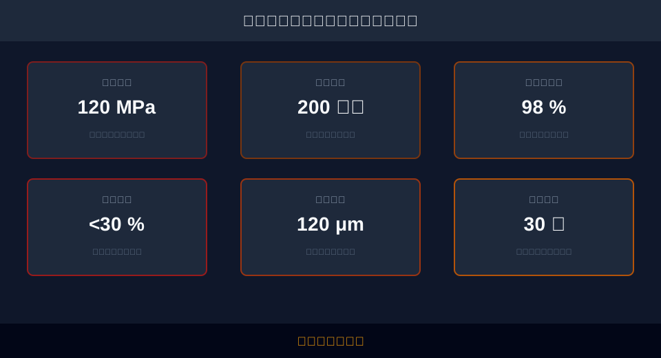
As the core load-bearing component of a crane, the main girder's welds are highly susceptible to microscopic defects under alternating stress. Taking a general-purpose overhead crane with a Rated Lifting Capacity of 50t and a Span of 28.5m as an example, the stress amplitude at the bottom flange weld near the mid-span can reach 120 MPa during full-load hoisting and braking. This high-frequency stress cycling is the fundamental cause inducing fatigue cracks.
Beyond alternating stress, welding residual stress and stress concentration are key contributing factors. At the fillet welds between the web plate and the flange plate, local stress concentration coefficients are often elevated due to abrupt geometric changes. When the equipment frequently performs emergency braking within the anti-collision safety distance, impact loads further amplify the stress peaks in these areas, accelerating crack initiation and propagation.
"According to fatigue test data, Q345B steel subjected to alternating loads with a stress amplitude of 120 MPa typically has a fatigue life of around 2 million cycles. If actual operating conditions exceed this limit, micro-cracks will first appear in the heat-affected zone (HAZ) of the weld."
⚠️ Note
During routine inspections, special attention should be paid to stress concentration areas such as the middle third of the main girder span, end carriage connections, and diaphragm welds, as these are high-risk zones for cracks.
Principles and Comparative Application of Non-Destructive Testing Technologies for Main Girder Weld Cracks
Detecting cracks is a prerequisite for repair, making the selection of appropriate inspection methods crucial. Currently, mainstream non-destructive testing (NDT) technologies include Magnetic Particle Testing (MT), Ultrasonic Testing (UT), and Penetrant Testing (PT). Each method has specific scopes of application and sensitivity limits, requiring comprehensive selection based on the location and depth of the cracks.
Magnetic Particle Testing is primarily used for detecting surface and near-surface defects, achieving a detection sensitivity down to 0.1 mm, which makes it ideal for identifying tiny cracks on the surface of flange plates. Ultrasonic Testing utilizes sound waves with a frequency of 2.5 MHz reflecting within the metal to precisely locate deep internal cracks, with a depth resolution error controlled within 15 dB. For more details on main girder weld crack detection, please refer to relevant technical literature.
📊 Comparison of NDT Technologies for Main Girder Weld Cracks
| test method | ApplicableDefectType | DetectionDepth/Sensitivity | Surfacerequirements |
|---|---|---|---|
| Magnetic Particle Testing (MT) (MT) | Surface and Near-SurfaceCrack | Surface0.1mm,Near-Surface2mm | Requires Grinding to Bare Metal |
| Ultrasonic Testing (UT) (UT) | Deep InternalCrack、Lack of Fusion | DepthResolution±1mm | Requires Couplant,Flat Surface |
| Penetrant Testing (PT) (PT) | Surface-BreakingCrack | Surface-Breaking Only,width≥0.01mm | Requires Strict Cleaning and Drying |
In practical engineering, a combination of inspection methods is often required to ensure no defects are overlooked. The following table compares the cost and efficiency of different test methods, providing a selection basis for device management professionals.
📊 Cost and Efficiency Evaluation of Non-destructive Testing Methods
| test method | Single PassDetectioncost | DetectionEfficiency | operator qualificationrequirements |
|---|---|---|---|
| Magnetic Particle Testing (MT) (MT) | Lower | Fast,Suitable for Large Area Scanning | MT IGrade orIIGrade |
| Ultrasonic Testing (UT) (UT) | Medium | Slower,Requires Point-by-Point Waveform Analysis | UT IIGrade orIIIGrade |
| Penetrant Testing (PT) (PT) | Low | Slow,Requires Waiting for Penetration and Development | PT IGrade orIIGrade |
"Industry field data shows that combining Magnetic Particle Testing (MT) with Ultrasonic Testing (UT) reduces the missed detection rate of main girder weld defects to under 2%, significantly enhancing operational safety."
💡 Tip
Before performing magnetic particle or penetrant testing, thoroughly remove oil, rust, and old paint from the weld surface. Failure to do so can obscure defect indications or lead to missed detections.
Weld Repair Process & Parameters for Bridge Crane Main Girder Cracks
Once a crack is confirmed, a scientific repair procedure is critical to restoring structural strength. Before welding, the crack must be completely removed using carbon arc air gouging or an angle grinder, followed by preparing an appropriate groove. For main girder flange plates thicker than 12mm, V-grooves or X-grooves are typically used, with the groove angle controlled at approximately 60° to ensure full root penetration.
Preheating and interpass temperature control are key to preventing cold cracking. For Q345B material, preheat the weld zone and 50mm on either side to 150°C before welding. During the process, strictly maintain the interpass temperature between 200°C and 250°C. In heavy-load custom projects, Kelude Heavy Industry often employs multi-layer, multi-pass welding with low current and fast speed to reduce heat input and minimize welding deformation.
Calculating and controlling welding heat input is vital. For example, in Shielded Metal Arc Welding (SMAW), the heat input formula is Q = (U × I) / v. If the arc voltage U is set to 24V, the welding current I to 180A, and the welding speed v to 3mm/s, the calculation yields: Q = (24 × 180) / 3 = 1440 J/mm. This value must be strictly kept within the limits defined in the Welding Procedure Qualification Record (PQR) to prevent grain coarsening in the heat-affected zone.
"The PQR indicates that for high-strength low-alloy structural steel, exceeding a heat input of 2500 J/mm reduces impact toughness in the heat-affected zone by approximately 30%. Therefore, multi-layer, multi-pass welding is mandatory to limit single-pass heat input."
⚠️ Note
Post-weld slow cooling is mandatory. Cover the weld area with asbestos cloth to allow it to cool naturally or in a furnace to room temperature. Avoid rapid cooling, which can induce new quenching cracks.
Quality Acceptance Standards & Residual Stress Relief After Repair
Completion of welding does not mean the end of maintenance; strict quality acceptance is the last line of defense for safety. Visual inspection is the first step, requiring a smooth weld profile free of undercut, porosity, or slag inclusion, with weld reinforcement controlled between 0–3mm. Subsequently, non-destructive re-inspection is required, typically mandating 100% Ultrasonic Testing (UT) meeting Level II acceptance criteria.
Since welding generates significant residual stress that can compromise the main girder's stiffness and fatigue life, stress relief is essential post-repair. Common methods include vibratory stress relief and thermal stress relief. Vibratory stress relief uses a vibrator to induce resonance, relaxing residual stresses through alternating stress. Post-treatment requires a residual stress reduction rate of ≥30%, with a resonance frequency deviation of ≤2%.
Before returning the equipment to service, the main girder camber must be re-measured. If the mid-span deflection exceeds 1/700 of the span, the anti-sway algorithm in the control system must be recalibrated to ensure smooth suspended load movement and reduce secondary damage to welds from dynamic impact loads.
"Acceptance specifications explicitly require that non-destructive re-inspection of repaired welds on critical load-bearing components be completed within 48 hours. If vibratory stress relief is used, the blind-hole method must be employed to measure residual stress values before and after treatment to verify effectiveness."
💡 Tip
For main girder welds subjected to dynamic loads, it is recommended to perform ultrasonic re-inspection 24 hours after welding to rule out delayed cracking, ensuring the accuracy of test results.
Daily Preventive Maintenance & Lifecycle Extension Strategies for Crane Girders
Beyond reactive repairs, establishing a robust preventive maintenance system is essential to fundamentally reduce crack occurrence. Routine inspections should occur at least monthly, focusing on surface corrosion, paint cracking, or minor deformation. For equipment exposed to corrosive environments, anti-corrosion coating thickness must be ≥120μm, with regular touch-ups to prevent substrate thinning due to corrosion.
Load management is key to extending weld life. Overloading is strictly prohibited, as it exponentially increases stress amplitude and accelerates fatigue damage. Operators should avoid sudden reverse gear engagement and emergency braking; smooth operation significantly reduces alternating impact loads. Upon delivery, Kelude Heavy Industry typically provides comprehensive operator training to reduce structural damage caused by human factors at the source.
Implementing a lifecycle archive management system for equipment is also indispensable. Recording data from each inspection, repair locations, and replaced components allows for data analysis to predict remaining life. Statistics show that implementing preventive maintenance extends overhaul cycles by 3 years and reduces overall maintenance costs by approximately 15%.
"Life cycle cost (LCC) analysis indicates that preventive maintenance investment accounts for only 15% of total operation and maintenance costs but prevents unplanned downtime losses worth up to 70%, delivering significant economic benefits."
⚠️ Warning
Never weld temporary lifting lugs or brackets in the main girder’s tension zones, such as the bottom flange. These additional weld seams introduce new stress concentration points that can easily trigger irreversible structural fatigue cracks.
Frequently Asked Questions
Q: Can minor cracks in the main girder weld seam be simply ground off?
A: If the crack depth is less than 0.5mm and non-destructive testing confirms it has not propagated, it can be eliminated by grinding with a smooth transition. However, if the crack is deep or located in a high-stress area, repair welding is mandatory; simple grinding cannot restore structural strength.
Q: What is the approximate cost of repairing main girder weld seams via welding?
A: Costs are influenced by crack length, repair complexity, and downtime. Expenses typically include detection, materials, labor, and stress relief. A specific quotation requires evaluation based on site survey results, subject to the actual contract.
Q: How soon after welding should re-inspection be conducted?
A: An initial ultrasonic re-inspection must be performed within 24 to 48 hours post-welding to rule out delayed cracks. After the equipment enters operation, tracking inspections are recommended at 3 months and 6 months to confirm no propagation before transitioning to routine inspection cycles.
Q: How do you determine if a main girder weld crack has penetrated through?
A: Surface penetration or magnetic particle testing only reveals surface-breaking cracks. To determine if a crack has penetrated through, ultrasonic testing must be used to measure crack depth, or drilling may be required for exploration in suspicious areas. If penetration is confirmed, immediate shutdown and a specialized reinforcement plan are necessary.
In summary, detecting and repairing weld cracks in overhead type crane main girders is a systematic engineering process requiring rigorous craftsmanship and strict acceptance standards. With deep expertise in heavy load customization, Kelude Heavy Industry provides comprehensive solutions ranging from structural optimization to full lifecycle maintenance, ensuring safe and efficient equipment operation.
