

Technical Encyclopedia of Common Questions on Crane Safety and Protection: Four Major Safety Systems—Limit Switches, Overload Protection, Lightning Protection, and Wind Protection
📌 Crane safety and protection involves 14 key questions and answers across four major systems: limit switches, overload limiters, lightning protection grounding, and wind-resistant anchoring.This article systematically outlines the functional principles, calibration standards, troubleshooting procedures, and compliance requirements for crane safety devices across four dimensions: overload protection, travel limit switches, lightning protection grounding, and wind safety. It covers core safety standards such as GB/T 3811-2008, TSG Q7016-2016, GB 50057, and JGJ 276.
Overview of Security System Categories
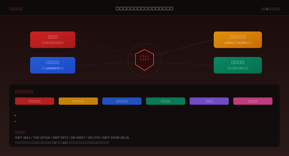
Crane safety protection systems are essential for ensuring the safe operation of equipment and the personal safety of operators. The FAQs on safety devices in the Krude Heavy Industry Technical Knowledge Base cover four core systems: overload limiters (105% pre-alarm / 125% circuit-breaking), hoist height limiters (counterweight type / worm gear type / photoelectric type), lightning protection and grounding systems (grounding resistance ≤ 4 Ω / SPD surge protector configuration), and wind safety devices (anemometers / rail clamps / anchoring devices). The following presents common technical Q&As categorized by system, with each entry labeled with the corresponding national standard clause number.
| Security System | Core Equipment | Key Parameters | Core Standards |
|---|---|---|---|
| Overload Protection | Overload Limiter | 1051 TP3T Alert / 1251 TP3T Stop-Loss | GB/T 3811-2008, Section 5.6 |
| Travel Limit | Lifting Limit Switch / Travel Limit Switch | Distance from the hook to the drum: ≥200 mm | GB/T 3811-2008, Section 5.7 |
| Lightning Protection and Grounding | Grounding System / SPD Surge Protector | Ground resistance ≤ 4 Ω / Quarterly inspection | GB 50057/TSG Q7016-2016 |
| Wind Protection and Safety | Anemometer / Rail Clamp / Anchoring Device | Alarm and power cutoff when wind speed is ≥20 m/s | JGJ 276/GB/T 3811-2008 |
Frequently Asked Questions About Overload Limiters
The overload limiter is one of the most critical safety devices on a crane; its function is to automatically cut off the hoisting power circuit and trigger an audible and visual alarm when the hoisting load exceeds the rated capacity. The standard alarm thresholds are 105% (pre-alarm) and 125% (forced cut-off) of the rated load, with a response time of no more than 1 second. Sensor types include tension sensors (mounted on the fixed pulley shaft end), pressure sensors (mounted on the hook beam), and torque limiters (suitable for luffing cranes). The calibration cycle is once every 6 months in accordance with TSG Q7016-2016 requirements; calibration covers zero-point drift, linearity, repeatability, and alarm threshold accuracy. Common malfunctions include sensor signal drift (caused by changes in temperature and humidity; replacement is required if the error exceeds ±3%), broken control wires (a high input signal after a break causes false alarms), and abnormal instrument displays (typically caused by poor contact or power fluctuations). As part of daily routine inspections, a no-load test should be conducted before the first load is applied to confirm that the self-test has passed and that there are no abnormal alarms.
Frequently Asked Questions About Hoist Limit Switches and Travel Limit Switches
|
🔴 Sledgehammer-style As the hook rises, it pushes the counterweight lever, triggering the limit switch. Although the design is simple, it may be accidentally triggered by the swinging of the wire rope. This system is suitable for indoor cranes with minimal environmental interference. |
🔵 Worm gear type A worm gear reducer connected to the end of the drum shaft is used to count revolutions; this method offers high precision but requires recalibration after mechanical wear. It is suitable for frequent hoisting operations and applications requiring precise height control. |
🟢 Photoelectric Install the photoelectric sensor at the specified height; its non-contact triggering mechanism is suitable for clean environments. It features fast response times and a long service life but is sensitive to dust and oil, making it suitable for cleanrooms. |
Adjustment Standards for the Hoisting Height Limit Switch: When the hook is raised to its limit position, the distance between the upper edge of the pulley block and the drum must be ≥200 mm (for electric hoists) or ≥100 mm (for overhead cranes). After adjustment, perform three repeated trigger tests to verify reliable operation.
Travel limit switches are installed at both ends of the track to control the crane’s movement within the set range; a buffer distance of ≥500 mm must be maintained at both end positions.
Frequently Asked Questions About Anti-Disengagement Devices and Emergency Stops
An anti-disengagement device is a safety component designed to prevent the load from accidentally disengaging from the hook during the lifting process; it creates a sealed space at the hook opening using a spring-loaded clamping plate. Key points for routine inspection include: the smooth operation of the spring-loaded pressure plate (it should automatically spring back when pushed manually); the clearance between the pressure plate and the tip of the hook (≤ 5% of the hook opening width); and spring fatigue deformation (no permanent deformation visible to the naked eye). The emergency stop button (red mushroom-head button with a yellow or red base) cuts off the main power supply upon activation, immediately halting all mechanisms. Standards require that each crane be equipped with at least one emergency stop button, which must be located in a conspicuous position in both the operator’s cab and the control station; its operational reliability must be tested once a week. Reset is achieved by turning clockwise to pull out or using a key; the use of self-resetting buttons as emergency stop devices is strictly prohibited (GB 16754-2008 stipulates that emergency stops must be manually reset).
Frequently Asked Questions About Lightning Protection Grounding and Electrical Safety
A lightning protection grounding system for outdoor cranes is a critical measure for ensuring equipment safety during the thunderstorm season. For a comprehensive safety protection system, please refer toThe Complete Guide to Crane Safety. In accordance with the requirements of GB 50057-2010 and TSG Q7016-2016, the lightning protection grounding resistance for outdoor cranes shall not exceed 4 Ω, and the grounding system shall be tested quarterly (and must be tested annually before the start of the thunderstorm season). The grounding system includes natural grounding electrodes (utilizing the crane rails and foundation reinforcing bars) and artificial grounding electrodes (vertical grounding rods or horizontal grounding grids). Rail grounding requirements: The two rails must be bonded using copper-core wire with a cross-sectional area of ≥50 mm², with bonding intervals of ≤30 m; At rail joints, flat steel or copper braided tape shall be used for bonding to ensure electrical continuity. SPD surge protectors shall be installed at the power supply input and control signal ports, with a rated discharge current of ≥20 kA (for power supply types) or ≥5 kA (for signal types). Regarding electrical safety, the insulation resistance shall not be less than 1 MΩ (measured with a 500 V megohmmeter), and the withstand voltage test shall be 1,500 V for 1 minute without breakdown or flashover. All products manufactured by Krude Heavy Industry undergo the aforementioned electrical safety tests in accordance with 100%.
Frequently Asked Questions About Wind Protection and Anchoring Devices
Wind safety for outdoor gantry cranes is a frequent compliance issue covered by both GB/T 3811-2008 and JGJ 276. In accordance with the requirements of these standards, outdoor gantry cranes must be equipped with three levels of wind protection devices:
Level 1 (Operating Status)— The anemometer monitors wind speed in real time; when the wind speed reaches or exceeds 20 m/s, an alarm is triggered and the power supply is automatically cut off.
Level 2 (Non-operational)—The rail clamp automatically clamps the rail when the equipment is not in operation; the clamping force must be sufficient to withstand the lateral thrust caused by wind speeds of 40 m/s.
Level 3 (Extreme Weather)—The anchoring system is secured using pre-embedded ground anchors or concrete anchor blocks, and, in conjunction with wind-resistant guy wires, forms a redundant design.
Key points for routine inspections include: wear on the rail clamps (replace if wear exceeds 5 mm), rust on the anchoring devices (derust and repaint annually), and calibration of the anemometer (compare with a standard anemometer once every six months).
When multiple cranes share the same track, each crane must be equipped with its own wind-resistant device; anchor points must not be shared.
Frequently Asked Questions (FAQ)
Q: Which national standards cover crane safety protection?
Answer: The main standards include GB/T 3811-2008 (the chapter on safety requirements in the Code for Design of Cranes), TSG Q7016-2016 (Rules for Periodic Inspection of Lifting Machinery), GB/T 5972-2016 (Maintenance, Inspection, and Scrapping of Wire Ropes), GB 50057 (Code for Design of Lightning Protection for Buildings), JGJ 276 (Technical Code for Safety of Lifting and Hoisting Operations in Building Construction), and GB/T 20438 (Functional Safety of Electrical, Electronic, and Programmable Electronic Safety-Related Systems). The specific clause numbers for each category of safety device are indicated in the Q&A section.
Q: What is the inspection interval for overload limiters? What does the inspection cover?
Answer: In accordance with the requirements of TSG Q7016-2016, overload limiters must be calibrated once every 6 months. The calibration includes: zero-point drift testing (the output signal under no-load conditions should be within ±2% of the initial value), linearity check (apply 25%/50%/75%/100%/110% of the rated load and record the corresponding output values), repeatability test (three tests with the same load; error ≤ ±1%), alarm threshold verification (pre-alarm at 105% of the rated load; cut off the hoisting power circuit at 125%). The sensor must be replaced if the signal drift exceeds ±3%.
Q: What wind-protection safety devices must be installed on outdoor gantry cranes?
Answer: In accordance with the requirements of GB/T 3811-2008 and JGJ 276, outdoor gantry cranes must be equipped with an anemometer (which triggers an alarm and automatically cuts off the power supply when wind speeds reach ≥20 m/s), rail clamps (which automatically clamp the rails when not in operation, with a clamping force capable of withstanding lateral wind forces from 40 m/s), anchoring devices (pre-embedded ground anchors or concrete anchor blocks), and wind-resistant guy wires. This three-tier wind protection system provides a redundant design to ensure equipment safety during extreme weather conditions. Krude Heavy Industry equips all outdoor gantry cranes in accordance with these standards.
Q: What are the requirements for the grounding resistance of crane lightning protection systems? What is the inspection frequency?
Answer: According to the requirements of GB 50057-2010 and TSG Q7016-2016, the lightning protection grounding resistance for outdoor cranes should not exceed 4 Ω, as measured using a grounding resistance tester. Inspection frequency: Routine inspections should be conducted quarterly, and a special inspection must be performed annually before the start of the thunderstorm season. If the grounding resistance does not meet the standard, corrective measures may include increasing the number of grounding electrodes (in parallel), deepening the burial depth of grounding electrodes (≥2.5 m), using resistance-reducing agents, or installing external grounding leads. The cross-sectional area of track bonding wires shall be ≥50 mm² copper core wire, with a spacing between bonding points of ≤30 m.
