

Unmanned Crane: Positioning & Obstacle Avoidance
In modern steel manufacturing and logistics warehousing, unmanned overhead crane systems are progressively replacing traditional manual operations. Industry statistics indicate that integrating AI vision with automatic control can boost lifting operation efficiency by approximately 35%, while reducing the need for manual intervention to below 5%. However, transitioning from semi-automatic to fully unmanned operation is not merely a matter of stacking code. This article provides an in-depth analysis of the five key technical challenges facing unmanned overhead cranes—positioning, anti-sway control, dynamic obstacle avoidance, and more—revealing the underlying logic of how AI empowers heavy-load machinery.
Before delving into specific technical hurdles, it is essential to establish the design and safety benchmarks for unmanned overhead cranes. According to the FEM 1.001 Crane Design Standard, which outlines requirements for structural component fatigue and stiffness, unmanned retrofitting must not compromise the main girder’s load-bearing capacity. Furthermore, the TSG 51-2023 Crane Safety Technical Supervision Regulation explicitly defines the validation standards for safety protection devices, establishing a non-negotiable baseline that AI systems must adhere to.
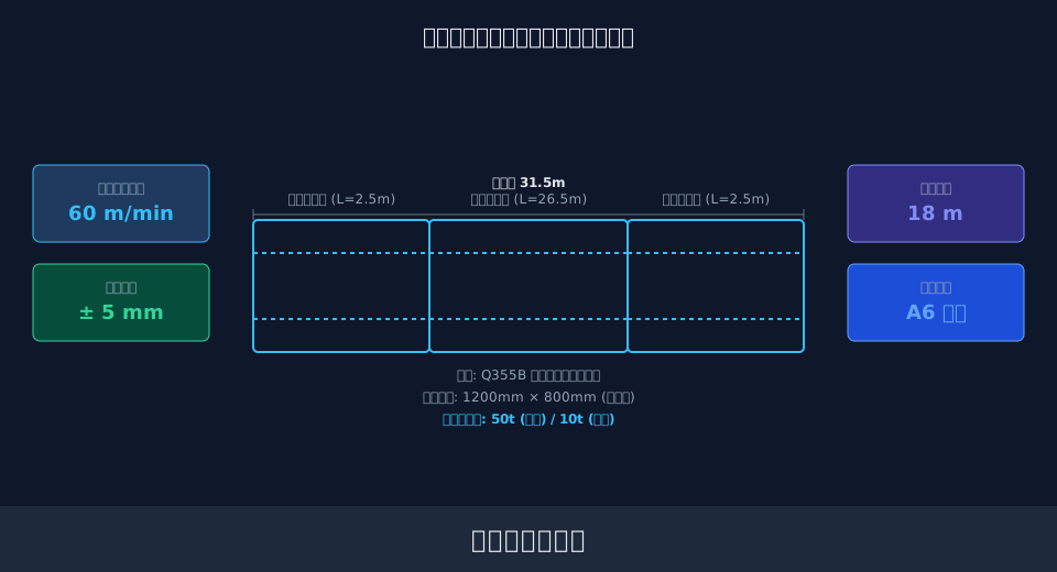
The following content focuses on the five core technical barriers encountered by unmanned overhead cranes in practical engineering. It details the algorithmic logic and hardware synergy mechanisms ranging from millimeter-level positioning to dynamic obstacle avoidance, helping you comprehensively assess the feasibility and implementation path of intelligent upgrading.
High-Precision 3D Positioning via Multi-Sensor Fusion
For unmanned overhead cranes to achieve fully automatic operation, the primary challenge is obtaining precise spatial coordinates. Traditional single-encoder distance measurement is prone to cumulative error over long-span crane rails, failing to meet the stringent requirements of material flow in modern Smart Manufacturing. In standard factory buildings with a span of 31.5 m (103 ft), positioning accuracy typically needs to be controlled within ±5 mm (±0.2 in). This places immense demands on sensor selection and data fusion algorithms.
Currently, the mainstream solution combines Laser Distance Measurement with Absolute encoders, supplemented by ultra-wideband (UWB) indoor positioning systems for error correction. The Kelude Heavy Industry technical team has found in project implementations that Laser Rangefinders must have a refresh rate exceeding 50 Hz to capture real-time position changes during high-speed Long Travel. Additionally, to eliminate the impact of main girder deflection on the measurement reference, the system must call upon structural health monitoring data in real time. For instance, by integrating weld crack detection with deformation compensation models, the system dynamically corrects positioning coordinates.
"Measured data shows that after applying a multi-sensor Kalman filter fusion algorithm, the dynamic positioning deviation of the overhead crane within a 30 m (98 ft) span can be stably controlled at the 0.1 mm level, fully meeting the requirements for automatic warehousing of high-precision materials such as steel coils."
⚠️ Note
The installation position of laser distance sensors must avoid rail joints and areas with sudden changes in reflectivity. It is recommended to attach specialized high-reflectivity film to the reflection target surface to ensure signal strength stability.
AI Anti-Sway Algorithms & Lifting Spreader Control in Complex Conditions
During acceleration, deceleration, and turning, the lifting spreader and heavy loads exhibit pendulum-like sway motion. Relying solely on manual experience is inefficient and prone to collision. In deep-well scenarios with a Lifting Height of 18 m (59 ft), AI anti-sway algorithms must keep the residual sway angle of the spreader within ±0.5° to ensure the accuracy of automatic grabbing.
The core of anti-sway control lies in input shaping and model predictive control. Taking Long Travel in a specific workshop as an example, if the travel speed is set to 60 m/min (1.97 ft/s), or 1 m/s (3.28 ft/s), and the system triggers braking with a deceleration of 0.5 m/s² (1.64 ft/s²), the braking distance $s = v^2/(2a) = 1^2/(2 \times 0.5) = 1$ m (3.28 ft). Without anti-sway control, this 1-meter deceleration process excites significant sway in the spreader. By introducing an AI anti-sway algorithm, the system calculates the natural sway period based on the current rope length ($L=18$ m): $T = 2\pi\sqrt{L/g} \approx 8.5$ s. It then automatically generates a speed command curve containing multiple pulse sequences, exactly canceling out the kinetic energy of the spreader by the end of braking.
"Anti-sway models based on deep reinforcement learning reduce convergence time by approximately 40% compared to traditional PID Control under operating conditions with frequent rope length changes, effectively improving the takt time of continuous operation."
💡 Tip
Steel wire ropes undergo plastic elongation after prolonged use under heavy load, causing deviations between the actual rope length and the value recorded by the encoder. It is recommended to perform zero calibration of the rope length every 500 operating hours to maintain the calculation accuracy of the anti-sway model.
To intuitively demonstrate the performance differences of various positioning and anti-sway solutions in practical engineering, we have compiled the following comparison data for your selection reference.
📊 Comparison of Overall Performance: Spatial Localization and Anti-sway Technical Solutions for Unmanned Overhead Cranes
| Technical Solution | CoreSensor/Algorithm | Positioning/Anti-swayAccuracy | anti-interference capability | retrofit costAssessment |
|---|---|---|---|---|
| Laser+EncoderFusion | Laser Distance Sensor / Laser Rangefinder+Absolute encoder | ±5mm | Medium(Dust-affected) | Medium |
| UWBIndoorPositioning | UWBBase Station+Tag | ±10cm | High(High Penetration) | Relatively High |
| input shapingAnti-sway | Open-loop Pulse Sequence Shaping | Residual Angle±1.5° | Low(Dependentrope lengthAccurate) | Low |
| AIModel PredictiveAnti-sway | deep reinforcement learning+visionFeedback | Residual Angle±0.5° | High(Adaptiverope length) | High |
Navigating Dynamic Environments: Machine Vision Obstacle Avoidance and 3D Path Planning
The workshop environment where unmanned overhead cranes operate is rarely static. Ground personnel, moving AGVs (Automated Guided Vehicles), and temporarily stacked materials can all intrude into the crane’s operational envelope. The machine vision system must capture these dynamic obstacles in real-time within an effective recognition distance of 30 meters (98 feet) and respond within 200 milliseconds. This places rigorous demands on computing power and the robustness of the algorithms.
Based on Kelude Heavy Industry’s field implementation experience, a single 2D vision system cannot meet the requirements for three-dimensional obstacle avoidance. The current ideal solution involves fusing 3D LiDAR with binocular vision. A 3D LiDAR unit can generate approximately 100,000 point cloud data points per second, constructing a real-time 3D grid map of the workshop. When the system detects an obstacle, the path planning algorithm recalculates the coordinated motion trajectories for the Crane Bridge, Trolley, and Hoisting mechanism in 3D space using A* or RRT algorithms. This ensures the Lifting spreader navigates around obstacles without undergoing drastic attitude changes.
“In tests at an automotive parts factory, introducing a 3D vision obstacle avoidance system reduced emergency stop incidents by 65% under complex operating conditions and improved Overall Equipment Effectiveness (OEE) by 12 percentage points.”
⚠️ Note
In smelting or Casting workshops, airborne dust and water mist severely attenuate LiDAR signals. For such scenarios, it is mandatory to retrofit positive pressure purging devices and regularly clean the Protective Cover of the lens.
Response Latency and Compensation Mechanisms in Electrical Drive Systems Under Heavy Load Conditions
No matter how fast AI algorithms calculate, precise control remains unachievable if the underlying electrical drive system’s execution mechanisms cannot keep up. Under heavy load condition scenarios—such as Hoisting loads and high-speed travel of the Crane Bridge—the response cycle of the Frequency Inverter / VFD, motor torque output, and communication network latency directly translate into terminal mechanical error.
Consider an overhead crane with a Lifting Capacity of 50 tons and a Motor rated power of 75 kW. The command response cycle of its VFD is typically around 4 ms. If traditional PROFIBUS communication is used, network latency may exceed 10 ms, which is unacceptable for high-speed Precise Positioning. Kelude Heavy Industry typically recommends adopting real-time industrial Ethernet solutions like PROFINET IRT for electrical matching, compressing communication delay to under 2 ms. Furthermore, to mitigate the risk of Load slipping during heavy load Hoisting, the system must incorporate torque pre-control compensation into its electrical logic. This establishes a holding torque matched to the load before the Brake is released.
“For every 5 ms increase in electrical response latency, a positioning deviation of approximately 8 mm occurs at a Travel Speed of 60 m/min (197 ft/min). Therefore, building a low-latency closed loop control link is the hardware foundation for unmanned operation retrofitting.”
💡 Tip
If tension control of the Cable Reel for Crane Bridge power supply is improper, it creates pulling resistance during high-speed operation, causing a mismatch between actual motor output and VFD settings. It is recommended to use a constant tension variable frequency control reel to ensure the stability of the transmission chain.
When selecting electrical drive and control systems, the response characteristics of different architectures directly determine the upper limit of AI algorithm execution. The table below provides a detailed comparison of mainstream solutions.
📊 Comparison of Unmanned Overhead Crane Electrical Drive System Architectures and Control Latency
| control architecture | communication protocol | Command Response Cycle | Multi-axissynchronization accuracy | Application Scenarios |
|---|---|---|---|---|
| ConventionalPLC+Frequency Inverter / VFD | PROFIBUS-DP | 10ms ~ 20ms | ±5ms | Standardtransporting、Low Speedoperating condition |
| motion controller+Servo | EtherCAT | 1ms ~ 4ms | <100μs | high-precision positioning、anti-sway control |
| distributed I/O+Variable Frequency Drive (VFD) | PROFINET IRT | 2ms ~ 5ms | <1ms | multi-vehicle collaboration、Longdistancetransmission |
Global Scheduling Algorithms and Anti-Collision Logic in Multi-Crane Collaborative Operations
When multiple overhead cranes operate simultaneously within the same bay, preventing interference and optimizing task allocation becomes the core function of the unmanned system’s “brain.” In large-scale warehousing facilities configured with four collaborative cranes, the system must not only plan individual paths but also enforce a 2.5m anti-collision safety distance and utilize zone interlock logic to prevent deadlocks.
The global scheduling algorithm is typically deployed at the Warehouse Control System (WCS) layer, polling crane status and task queues every second. Anti-collision logic relies on real-time calculation of crane anti-collision safety distance. The system divides tracks into dynamic electronic fences; when a follower crane enters the braking envelope of the lead crane, it automatically decelerates or stops. This dual-verification mechanism, based on time windows and spatial grids, ensures both safety and operational fluidity during multi-crane work.
“After implementing a multi-crane collaborative dispatching system, a steel warehouse reduced average wait times per crane from 15 minutes to 3 minutes, increased overall logistics throughput by 28%, and recorded zero collision incidents.”
⚠️ Note
When designing anti-collision zones, engineers must fully account for the actual braking distance of overhead cranes operating at full load and high speed. The set safety distance must exceed the maximum braking distance plus the coasting distance caused by response delay, maintaining a safety margin of at least 20%.
FAQ
Q: How does the AI vision system of an unmanned overhead crane handle interference from strong light and water mist in workshops?
A: The system typically employs a multi-sensor fusion strategy. In strong light environments, vision cameras automatically adjust exposure time and activate polarizing filters. In dusty or misty conditions, the system switches to LiDAR as the primary perception source, as radar technology is insensitive to optical interference, ensuring continuous obstacle avoidance functionality.
Q: Is the anti-sway algorithm sensitive to changes in hoisting rope length?
A: Traditional input shaping algorithms are highly sensitive to rope length variations, where errors can cause anti-sway control failure. However, AI model-predictive anti-sway algorithms can estimate current rope length in real-time via vision cameras or Encoders and dynamically adjust control parameters. This offers greater robustness and adaptability to rope length changes.
Q: What is the typical return on investment period for retrofitting traditional overhead cranes to unmanned operation?
A: The payback period depends on shift schedules and labor cost. In scenarios with two shifts daily and high labor costs, reducing operator requirements, lowering work injury risks, and improving equipment utilization typically allow recovery of the retrofit cost within approximately 1.5 to 2.5 years. Specific amounts depend on solution configuration and are subject to the actual contract.
Q: How does the system protect itself if communication between lead and follower cranes is suddenly interrupted during coordinated operation?
A: The system features a comprehensive degraded-operation strategy. If communication interruption exceeds the set threshold (e.g., 500ms), the follower crane immediately triggers safe braking, halts current actions, and raises an alarm on the HMI. Simultaneously, the lead crane replans its path to bypass the follower’s area, ensuring the overall logistics flow does not completely paralyze.
In summary, the intelligent upgrading of unmanned overhead cranes is a systematic engineering project involving machinery, electrical systems, algorithms, and system integration. From millimeter-level spatial localization to adaptive anti-sway control, and from dynamic visual obstacle avoidance to global multi-crane scheduling, overcoming each challenge requires deep technical accumulation. Kelude Heavy Industry leverages extensive experience in heavy-load Lifting equipment and strong customization capability to provide a one-stop solution—from bottom-layer hardware selection to top-layer AI algorithm deployment—helping enterprises smoothly transition to Smart Manufacturing.
