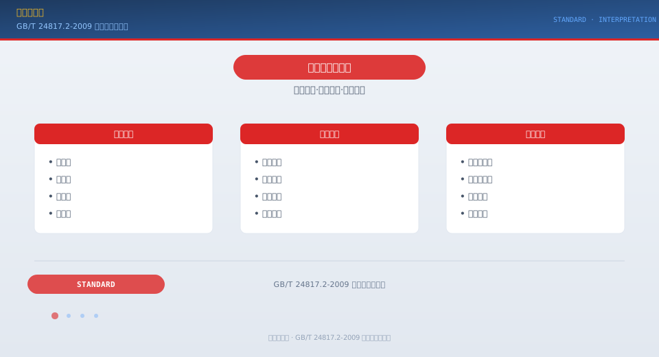
Mobile Crane Control Device Arrangement per GB/T 24817.2-2009
GB/T 24817.2-2009, "Lifting Appliances — Arrangement and Characteristics of Control Devices — Part 2: Mobile Cranes," is the dedicated design standard for the human-machine control interface of mobile cranes. Building on the general principles established in Part 1, this standard refines the layout requirements, operating direction characteristics, and special control functions for truck cranes, crawler cranes, all-terrain cranes, and rough-terrain cranes based on their specific operating characteristics.
GB/T 24817.2-2009 is Part 2 of the crane control device arrangement standard series. It provides specific provisions for the classification, layout, and operating characteristics of control devices on mobile cranes, addressing their unique control features and operational requirements. Because mobile cranes combine travel and hoisting functions in a single machine, the logical arrangement of controls directly impacts operating efficiency and safety. The following sections break down the key requirements of this standard.
Scope and Applicable Crane Types
GB/T 24817.2-2009 corresponds to ISO 7752-2:1985 (MOD) and is the second part of the GB/T 24817 series, focusing specifically on mobile cranes. The standard applies to the following crane types: truck cranes (including loader cranes), crawler cranes, all-terrain cranes, rough-terrain cranes, and telescopic boom crawler cranes. For these machines, the standard details the layout principles, operating direction consistency, functional zoning, and identification marking of control devices (joysticks, pushbuttons, switches, foot pedals, etc.) inside the operator cab or control cabin during hoisting operations. Because mobile cranes serve dual travel and lifting functions, their control layouts are inherently more complex than those of fixed base cranes — travel controls and hoisting controls must be clearly separated within the same space to prevent inadvertent operation.
Segregation of Travel and Hoisting Controls
What sets mobile cranes apart is that a single machine supports two fundamentally different operating modes: travel and hoisting. The standard explicitly requires that travel control devices and hoisting control devices be physically segregated into distinct zones:
Travel Control Zone — Travel controls such as the steering wheel, accelerator pedal, brake pedal, transmission lever, and turn signal switch must be positioned directly in front of the driver's seat, following automotive industry standards (e.g., GB 11562). The operation of this zone mirrors that of a standard road vehicle, ensuring the operator requires no additional training for on-highway driving.
Hoisting Control Zone — Hoisting controls, including the hoisting lever, luffing control lever, slewing control lever, boom extension/retraction lever, and outrigger levers, must be positioned directly in front of and on both sides of the hoisting operating position, with a clear physical separation or shielding from the travel control zone. The operating direction of the levers in the hoisting zone must comply with the general principles of Part 1: pull back to hoist, push forward to lower.
Mode Switching — A mode selector switch (key-type or pushbutton) must be provided to transition between travel mode and hoisting mode. This switch should be located between the two control zones within easy reach. Once switched to hoisting mode, certain travel controls must be automatically locked out (e.g., the transmission lever becomes inoperable during hoisting operations).
Standard automotive layout
Front and both sides
Interlock protection
Independent operation per outrigger
One at travel & one at hoist position
Mounted right of the seat
Specialized Control Functions for Mobile Cranes
Compared to fixed base cranes, mobile cranes incorporate several specialized control functions, and the standard sets out specific layout requirements for each:
Outrigger Controls — Outrigger extension and retraction must be managed from a dedicated control panel. Each outrigger requires two independent control actions: horizontal extension and vertical support. The controls must be positioned so the operator can observe the full outrigger movement from ground level or through the cab window. The outrigger panel must include green indicator lights for outriggers fully deployed and red warning lights for incomplete deployment.
Boom Extension/Retraction Controls — Telescopic boom cranes must be fitted with a boom extension/retraction lever (or proportional control handle). The control direction should correspond to the actual boom movement: push forward to extend, pull back to retract. For multi-section booms, the control may use either single-lever sequential operation (extending/retracting each section in sequence) or proportional synchronization control (all sections extending/retracting simultaneously with the controller automatically coordinating section speeds).
Load Moment Limiter (LML) Control Panel — The LML panel on a mobile crane must be positioned directly in front of the hoisting operating position, within ±15° of the operator's horizontal line of sight. The panel must display key parameters including actual load, rated load, load percentage, jib length, working radius, and boom angle. When the load ratio reaches 90%, an early warning is triggered (flashing yellow light plus buzzer). At 100%, an alarm sounds and automatic shutdown of dangerous-direction movements is initiated (allowing only movements in the safe direction).
Slewing Brake and Free Swing — The slewing mechanism must be equipped with a slewing brake control switch and a selector switch that permits free swing under specific operating conditions. Free swing is used for certain lifting procedures (e.g., alignment during wind turbine installation) and must be clearly marked on the control panel with an interlock protection that allows activation only under defined conditions.
Control Layout for Rotating Operator Cabs
Some large mobile cranes (such as all-terrain cranes) are equipped with a rotating operator cab that slews with the upper structure. The standard specifies particular control layout requirements for these cabs:
The seat in a rotating operator cab shall either pivot in tandem with the slewing platform or feature independent rotation (rotation range ≥180°), ensuring the operator always faces the boom during hoisting operations. The control console shall move in sync with the seat so that the joysticks and display instruments remain directly in front of the operator at all times. When the cab is rotated to a non-forward position, the travel control device shall be automatically locked or covered.
For large crawler cranes (Lifting Capacity ≥100t), the operator cab is typically positioned on the left or right side of the slewing platform. Standard requirements stipulate that the cab installation position must allow the operator to have a direct line of sight to the hook and load from a normal operating posture, with the lower edge of the front window no more than 800mm above the floor. If direct visibility of the hook is obstructed by the boom or mast, a camera assist system shall be provided. Kelude Heavy Industry strictly follows the zoning principles of ISO 12480 in the design of its mobile crane operator cabs, implementing dual hardware and software interlocks between travel and hoisting controls to ensure zero operator confusion.
| Control Functions | Operation Mode | Arrangement Position | special requirements |
|---|---|---|---|
| Hoisting / Lifting Control | joystick Forward/Backward | Right Side of Seat | With Micro-motion/Fast Lowering Mode Switch |
| luffing control | joystick Forward/Backward | Left Side of Seat | Working radius Luffing And Angle Luffing |
| Slewing Control | joystick Left/Right Thrust | Right-Hand Side of Seat | Switchable Free Swing Mode |
| boom extension/retraction | joystick/Proportional Handle | Left-Front of Seat | Sequence/Synchronization Telescoping Optional |
| Outrigger Control | Independentjoystick×4 | Below Side Window/Ground | Each Outrigger Independent Operation |
| torque limiting | Digital Panel+Push Button | Direct Front Horizontal Line of Sight | 90%early warning100%Cutoff |
Safety and Emergency Control Devices
Mobile cranes must be equipped with the following safety and emergency control devices: an Emergency Stop Button—a red mushroom-head pushbutton installed at both the travel control station and the hoisting control station. Pressing it immediately cuts off the engine throttle (or disengages the Hydraulic Pump power source) and applies full Brake application to all mechanisms. If the operator fails to respond to the Overload Alarm within 3 seconds by stopping the hazardous movement, the system must automatically shut down the dangerous direction and activate an Audible and Visual Alarm. Outrigger stability indicator—when any outrigger is not fully grounded or ground contact pressure is insufficient, a continuous Audible and Visual Alarm must be triggered, and Hoisting and slewing operations must be prohibited.
Mobile Crane Control Device Layout Requirements: Comparison Table
The comparison table below outlines the core Parameter configuration for the arrangement of control devices on Mobile Cranes, serving as a reference for selection and operational personnel.
| control device | Operating Functions | Arrangement Position | marking requirements |
|---|---|---|---|
| Hoisting / Liftingjoystick | Main Hoist Winch/Auxiliary Hoist Winch | Right-Hand Side of Seat | Arrow+Lifting Capacity Marking |
| luffing control lever | Jib Tilt | Left-Hand Side | Angle Indication |
| slewing control lever | Upper Structure Slewing | Left/Right-Hand Side of Seat | 360°Direction Indication |
| travelingtread plate | Crawler Track/Tire Drive | Foot Pedal Position | Forward/Reverse Marking |