

Crane Encoder Selection & Closed-Loop Control
In the evolution of smart cranes, precise position feedback is the foundation of automated operation. A bridge crane equipped with a high-resolution 2500-line encoder can achieve hoist positioning accuracy at the 0.05mm level—tens of times better than traditional open-loop control. However, in complex industrial environments, selecting the right encoder for specific operating conditions and building a stable closed-loop control scheme remains a practical challenge for many engineers. This article explores the core indicators for encoder selection and the implementation details of closed-loop control systems.
When selecting equipment and designing systems, you must strictly follow the electrical control and safety protection regulations in FEM 1.001 Crane Design Specification, while meeting the specific requirements for special equipment safety supervision outlined in TSG 51-2023 Crane Safety Technical Supervision Regulation. This ensures the compliance and reliability of the entire closed-loop system.
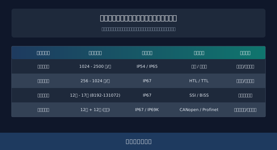
This guide starts by analyzing encoder types and parameters, then moves to closed-loop architecture design, cost assessment, and maintenance. Finally, it answers common questions about project implementation, providing a complete technical reference.
Encoder Types and Core Parameters for Smart Cranes
In the electrical control system of a smart crane, the encoder serves as the core element for position and speed feedback. Its type determines the upper limit of closed-loop control precision. Industrial encoders are primarily divided into incremental and absolute types. Incremental encoders output pulse sequences to reflect displacement, offering fast response and lower costs, but they lose absolute position data upon power loss, requiring a homing procedure each time the system starts. Absolute encoders output absolute position data directly via internal code disks, retaining data after power loss and significantly simplifying system initialization.
Two key indicators require careful consideration: resolution and Protection Rating (IP). For Long Travel Speed and Cross Travel / Trolley Travel mechanisms, a 2500-line/incremental encoder typically meets standard speed control needs. For hoisting mechanisms requiring high-precision positioning, a single-turn or multi-turn absolute encoder with 17-bit or higher resolution is recommended. Additionally, since crane environments often involve dust, oil, and vibration, the encoder’s housing should have at least an IP67 rating to protect internal optical or magnetic components from environmental erosion.
To understand how encoder parameters affect actual performance, consider this engineering case study: Assume a smart crane’s Long Travel Speed is set to 60m/min (1m/s), with a reduction ratio of 1:50 between the motor and wheels, and a Wheel Diameter of 0.4m. First, calculate wheel rotational speed: n1 = v / (π×D) = 1 / (3.14×0.4) ≈ 0.796 r/s. Next, calculate motor shaft speed: n2 = n1 × 50 = 39.8 r/s. If using a 2500-line incremental encoder, the pulse frequency per second is f = n2 × 2500 = 99500 Hz. With a PLC control sampling period of 10ms (0.01s), the pulses received per cycle are N = 99500 × 0.01 = 995. The control system uses a high-speed counter to process these 995 pulses, precisely calculating the real-time travel speed for accurate closed-loop speed control.
"Industry measured data shows that under identical conditions, hoisting mechanisms using high-resolution absolute encoders maintain repeat positioning accuracy within ±2mm. Compared to traditional open-loop or low-resolution systems, positioning error is reduced by approximately 85%, significantly improving the success rate of automated grabbing."
⚠️ Note
Do not blindly pursue ultra-high precision during equipment selection. In standard material handling scenarios, excessive encoder resolution increases computational load on the control system and may cause "high-frequency jitter" due to transmission backlash, reducing stability. Match precision reasonably based on the actual anti-collision safety distance requirements.
Closed-Loop Architecture and Anti-Interference Installation
Building a stable closed-loop control system requires not only high-performance encoders but also scientific architecture design and rigorous signal anti-interference processes. In a typical smart crane closed-loop architecture, a PLC or dedicated motion controller acts as the master station, receiving real-time position and speed feedback from the encoder. It calculates deviation against internal target trajectories and sends corrected control commands to the Frequency Inverter / VFD via industrial Ethernet protocols like Profinet or EtherCAT. The inverter adjusts motor output, forming a complete closed-loop control circuit.
However, crane sites contain strong electrical equipment like contactors and inverters, creating a harsh electromagnetic environment. Weak encoder feedback pulses are easily interfered with, leading to distorted position data or even uncontrolled system movement. Therefore, anti-interference installation is critical. Hardware-level interference suppression is the physical foundation required for advanced AI anti-sway algorithms to function effectively.
Strictly adhere to the following specifications for anti-interference installation:
First, use twisted-shielded Cable for signal lines. Ground the shield layer at only one end (the Control Cabinet side) to prevent ground loops from introducing high-frequency interference. Grounding Resistance must be strictly controlled below 4Ω.
Second, when routing Power Cable and signal cable in the Bridge girder, maintain a physical separation of at least 300mm. If crossing is unavoidable, intersect them at a 90-degree angle to minimize coupling area.
Third, install a Reactor or dv/dt Filter at the inverter output to reduce high-frequency harmonic interference caused by long cable capacitance. This ensures the purity of the feedback waveform.
"During the initial phase of a retrofit project for a rolling mill crane at a major Steel Mill, failure to strictly implement single-end grounding for signal cables caused frequent position feedback jumps and closed-loop oscillation during low-speed hoisting. After rectifying the grounding process and adding magnetic rings, the feedback jumps disappeared completely, ensuring smooth operation."
💡 Tip
When routing encoder cables over long distances (exceeding 50 meters), it is recommended to use encoders with line drivers (such as RS422 differential outputs) or install line receivers at the signal receiver end. This enhances common-mode rejection capabilities, ensuring data transmission integrity.
Encoder Selection Cost Analysis and Return on Investment Period
During the budget planning phase for Smart Crane projects, evaluating encoder selection costs is a critical step. From a direct procurement perspective, the unit price of an Absolute encoder is typically 1.5 to 2 times that of an Incremental encoder of the same specification. However, deciding solely based on initial purchase price often leads to the misconception of "cheap to buy, expensive to use." A comprehensive assessment must consider life cycle costs, including installation & commissioning expenses, maintenance costs, and hidden losses due to downtime.
Kelude Heavy Industry’s experience in heavy load customization projects indicates that while Absolute encoders have higher hardware costs, their zero-homing-free feature significantly reduces on-site commissioning time. For a large Smart Crane comprising Crane Bridge, Trolley, Hoisting/Lifting, and multiple auxiliary mechanisms, adopting an Absolute encoder solution can save approximately 60% of electrical commissioning labor hours. Additionally, by reducing mechanism wear during mechanical homing processes, subsequent maintenance frequency can be lowered by about 30%.
To clearly illustrate the structural differences in cost structures among various selection schemes, we have compiled the following comparative data:
The table below provides a detailed cost comparison of Incremental and Absolute encoders across three dimensions: initial investment, installation & commissioning, and post-maintenance, offering data support for project budgeting.
📊 Life Cycle Cost Comparison: Incremental vs. Absolute Encoders
| costDimensions | Incremental encoderSolution | Absolute encoderSolution | costVariance Analysis |
|---|---|---|---|
| Hardwareprocurement cost | Base Price(100%) | Approx. 150% - 200% | Initial Cost of Absolute Positioning Solutionprocurement costSignificant Increase |
| on-site commissioningLabor Hours | Requires Frequent HomingCalibration,Time-Consuming | Reads Immediately Upon Power-Up,Saves Approx. 60% Labor Hours | Absolute Positioning Solution Significantly Reduces Labor CostsCommissioningcost |
| Later Stagemaintenance cost | Batteryreplacement&MachineryHomingWear | Battery-Freedesign,maintenanceReduced Frequency 30% | Absolute Positioning Solution Under Long-Term Operationmaintenance costLower |
"Financial modeling for an automation project at a major port demonstrates the tangible ROI of upgrading hoisting mechanisms with multi-turn absolute encoders. Although this upgrade increased initial electrical investment by approximately $17,940, the project achieved a return on investment period of just 1.5 years. This was driven by a 15-day reduction in commissioning time and a 40-hour decrease in fault shutdown duration during the first year of operation."
⚠️ Note
When evaluating costs, do not overlook hidden expenses associated with supporting equipment. Multi-turn absolute encoders typically require PLC high-speed counting modules or dedicated gateways that support specific communication protocols (such as SSI, BiSS, or CANopen). The resulting increase in hardware cost within the Control Cabinet can sometimes exceed the price difference of the encoder itself. Final costs are subject to the actual contract.
Common Fault Diagnosis and Routine Maintenance for Closed-Loop Control Systems
After prolonged operation under heavy loads, Smart Crane closed-loop control systems inevitably encounter various faults. Field maintenance data indicates that issues related to the Encoder and its feedback loop account for approximately 15% of all electrical system failures. Common fault symptoms include sudden jumps in position feedback values, significant speed fluctuations, and system alarms indicating encoder disconnection or communication timeouts. Rapid and accurate diagnosis of these issues is critical for ensuring equipment availability.
Effective routine maintenance relies on standardized inspection protocols. We recommend conducting a thorough examination of the Encoder every six months. Key tasks include cleaning oil and dust from the Encoder surface, checking the tension and wear status of the Coupling or synchronous belt, and measuring the Insulation Resistance of the signal cable (which should be greater than 20MΩ). In harsh operating environments, such as high-temperature smelting workshops, the inspection cycle should be shortened to three months. Additionally, integrating regular weld crack detection allows for a comprehensive assessment of both the crane's structural health and its electrical control status.
When anomalies occur in the closed-loop system, maintenance personnel should follow the troubleshooting logic outlined below:
The table below details common fault symptoms, troubleshooting steps, and corrective actions for Encoders and feedback loops in closed-loop control systems, providing a quick reference guide for field maintenance teams.
📊 Troubleshooting Guide for Common Closed-Loop Feedback Loop Faults
| fault symptom | possible causeAnalysis | troubleshooting& Countermeasures |
|---|---|---|
| System Reportsencoder disconnection | signal cableOpen Circuit、Loose Connector or Abnormal Power Supply | multimeterMeasurementcableContinuity;Re-crimp Terminals;inspection 5V/24V supply voltageWithinpermissible deviationRange |
| At Low SpeedspeedHigh Feedback Fluctuation | CouplingSlippage、Encoder Disk Contamination or Strong Electrical Interference | TighteningCouplingScrews;Clean Encoder Disk;inspectionShielding LayerGroundingReliability Check,Add Magnetic Ring |
| Absolute encoderPosition Loss | Internal Battery Depletion or Strong Magnetic Interference | replacementSameModelspare / standbyBattery;Re-execute Absolute PositioningCalibration;inspectionPresence of Large [Equipment] NearbyFrequency Inverter / VFDInterference |
The Equipment Maintenance Manual explicitly states that for multi-turn Absolute encoders with battery buffering, batteries must be replaced while the system is powered on. Replacing them while powered off causes permanent loss of internal multi-turn count data, requiring extensive time to recalibrate.
⚠️ Warning
Before performing any electrical wiring or mechanical disassembly related to the Encoder, strictly implement Safety Operating Procedures: power off, verify de-energization, and lockout/tagout. Kelude Heavy Industry’s technical team emphasizes that hot-plugging encoder connectors can easily damage internal optocouplers, causing irreversible hardware failure.
Smart Crane Encoder Selection & Closed-Loop Control FAQ
During the design and retrofit of Smart Cranes, engineers and end-users often encounter questions regarding encoder selection and closed-loop control. Below are four representative FAQs, answered with practical engineering experience to guide your project decisions.
Q: How to quickly locate an encoder disconnection fault in a closed-loop control system?
A: First, check if the supply voltage at the PLC or Frequency Inverter (VFD) end within the Control Cabinet is normal. If power is stable, use a multimeter to test the continuity of the signal cable from the encoder connector to the cabinet terminal. If the cable is intact, inspect the connector terminals for oxidation or looseness, or try replacing the unit with an identical model to rule out hardware failure.
Q: What is the difference in Resolution between Incremental and Absolute encoders?
A: The Resolution of an Incremental encoder is typically expressed as pulses per revolution (e.g., 1024 PPR, 2500 PPR); higher values yield finer speed and distance measurement accuracy. An Absolute encoder’s resolution is measured in bits (e.g., 17-bit represents 131,072 unique positions per revolution). Absolute encoders generally offer significantly higher position resolution than standard Incremental types, making them suitable for ultra-high-precision positioning applications.
Q: Approximately how much does upgrading all vehicle encoders to Absolute type increase the overall retrofit cost?
From a pure hardware procurement perspective, the unit price of an Absolute encoder is 1.5 to 2 times that of an Incremental one, increasing total encoder hardware costs by about 60% to 80%. However, considering saved commissioning hours, reduced wear on homing mechanisms, and lower maintenance costs, the comprehensive life cycle cost increase is typically only 15% to 20%. Specific amounts are subject to the actual contract.
Q: Under coordinated operation conditions with multiple cranes, how does closed-loop control ensure synchronization accuracy?
Multi-machine synchronization relies not just on high-precision encoders but also on a robust master-slave control architecture. Typically, the master PLC synchronizes position feedback across all cranes in real-time via industrial Ethernet (e.g., EtherCAT). Using cross-coupling control algorithms, it dynamically compensates for positional Deviation between mechanisms, keeping synchronization errors within millimeter-level tolerances.
In summary, precise encoder selection and the scientific implementation of closed-loop control schemes are critical steps toward intelligent crane operations. With deep expertise in heavy-load customization, Kelude Heavy Industry provides full-process technical support—from initial operating condition analysis and simulation to final commissioning and delivery—helping your Material Handling systems achieve efficient, safe, and intelligent upgrades.
