

Wireless Remote Control Safety: Power & E-Stop Layout
In modern metallurgical and heavy machinery workshops, the Wireless Remote Control System has become a standard configuration for Smart Cranes. Statistics show that in 2023, the penetration rate of radio remote-controlled cranes in newly constructed factory buildings reached 65%, with each unit transmitting over 3,000 operation commands daily. This cordless operation significantly enhances flexibility but places higher demands on the safety of the control circuit. Without reliable power-off and emergency stop arrangements to handle signal anomalies or power failures, incidents such as load slipping or collision are highly likely. This article provides an in-depth analysis of the safe operation points for wireless remote control systems, detailing the logic for power-off protection and engineering standards for emergency stop circuit layout.
Before discussing specific layout schemes, we must rely on national technical specifications. According to the basic requirements for control circuit safety in the FEM 1.001 Crane Design Specification, the control circuits of all motion mechanisms must possess independent safety cut-off mechanisms. Furthermore, in compliance with the mandatory provisions of the TSG 51-2023 Crane Safety Technical Supervision Regulation, wireless remote devices must be equipped with hardware-level Emergency Stop Buttons, and their safety level must not be lower than the prescribed property class. These standards provide the legal basis for subsequent circuit design and hardware selection.
The following sections will comprehensively break down the key safety layout points for smart crane wireless remote control systems from five dimensions: power-off protection logic, emergency stop circuit design, anti-interference communication strategies, receiver relay layout, and periodic routine inspection standards, helping you build a solid equipment safety defense line.
Power-Off Protection Logic and Hardware Redundancy Layout for Smart Crane Wireless Remote Systems
Power management of the Radio Remote Control is the starting point of the entire safety chain. In practical applications of smart cranes, the control system's power-off protection must address not only battery depletion but also the risk of malfunctions caused by voltage fluctuations. The technical team at Kelude Heavy Industry has found during commissioning that reasonable power redundant design can reduce the system failure rate by more than 40%.
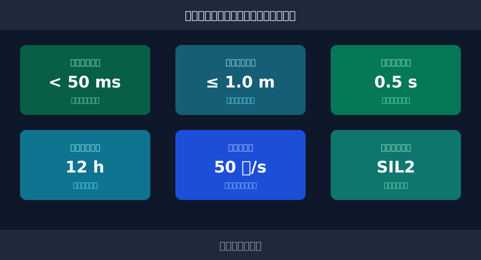
In terms of hardware layout, the internal structure of the remote control typically adopts a dual-power supply architecture. The main circuit is powered by large-capacity lithium batterys, providing an endurance time of up to 12 hours; the standby circuit maintains the transmission of critical signals through supercapacitors. When the main power supply voltage dips to 85% of the rated voltage, the system triggers a low-voltage alarm.
"According to relevant provisions of FEM 1.001, power-off protection of the control circuit should ensure that all motion mechanisms can stop immediately under any power failure condition, and mechanisms do not start unexpectedly due to residual voltage."
Regarding the layout of the receiver Control Cabinet, the power supply inlet must pass through an independent safety Circuit Breaker. Taking cable voltage drop calculation as an example: if the cable length is 100 m and the cross-section is 2.5 mm², with an operating current of 2 A and copper resistivity of 0.0175 Ω·mm²/m, the resistance of a single cable R = 0.0175 × 100 / 2.5 = 0.7 Ω. The total voltage drop of the two-wire loop ΔU = 2 × 2 A × 0.7 Ω = 2.8 V. If the system rated voltage is 24 V, the terminal voltage is 21.2 V, which remains within the range for reliable Contactors suction. Additionally, when planning the anti-collision safety distance of the crane, the coasting distance after power loss must also be calculated into account.
⚠️ Note
The battery low-voltage alarm threshold must be set above the reliable release voltage of the contactor. It is generally recommended to set it around 80% of the rated voltage to prevent frequent suction and release of the contactor due to critical voltage fluctuations, which could burn out the contacts.
Emergency Stop Button Circuit Design and Safety Level Verification for Radio Remote Controls
The Emergency Stop Button is the last line of defense against sudden emergencies, and its circuit design directly relates to personnel and equipment safety. In smart cranes, the emergency stop signal of the radio remote control must not only cut off the power supply but also trigger brake application. The safety level of the entire emergency stop circuit must meet SIL2 or PLd standards.
The hardware resistance of the emergency stop circuit must be strictly controlled. Practical tests show that when the total circuit resistance is <2 Ω, the reliability of signal transmission is highest. In engineering verification, we need to calculate the braking distance after triggering the emergency stop. Taking the travel mechanism as an example, assuming a travel speed of 60 m/min (i.e., 1 m/s) and a deceleration of 0.5 m/s², according to the kinematic formula s=v²/(2a), the braking distance s=1²/(2×0.5)=1 m. This means that after the emergency stop signal is triggered, the travel coasting distance must be controlled within 1 m.
"TSG 51-2023 clearly states that lifting appliances must be equipped with emergency stop devices. These devices should be able to cut off the total power supply, and their action should not depend on software control but must be a pure hardware-level physical cut-off."
At the receiver end, the emergency stop circuit typically adopts a dual-channel redundancy design. Two independent emergency stop relays are connected in series in the total contactor coil circuit. The system can only reset when both channels simultaneously detect that the emergency stop signal has been released. This design effectively avoids safety failures caused by a single point of failure.
💡 Tip
Emergency stop buttons should be equipped with yellow mushroom heads and red bases, and designed with protective covers to prevent accidental touches. In workshops with significant vibration, it is recommended to select buttons with a self-locking function to ensure they do not automatically pop up due to vibration after being pressed.
| Comparison Parameter | Traditional Wiredcontrol system | Radio remote controlcontrol system |
|---|---|---|
| emergency stopsignal transmissionMedium | PhysicalCableDirect Connection | Radio Waves+Receiver Hardware Disconnection |
| response delayTime | < 10ms | < 50ms |
| cableWearRisk | High(Core Breakage Susceptible to Towing) | None |
| safety levelVerification | SIL3 / PLe | SIL2 / PLd |
The table below compares the interference resistance and key parameters of mainstream wireless communication protocols in industrial environments, providing data-driven support for selection.
Interference Resistance & Key Parameters of Wireless Communication Protocols
| communication protocol | operating frequency band | Frequency Hopping Rate | Resistance toFrequency Inverter / VFDInterference Immunity |
|---|---|---|---|
| IndustrialWi-Fi | 2.4GHz / 5GHz | Adaptive | Medium |
| Proprietary Frequency Hopping Protocol | 433MHz / 868MHz | 50Times/s | Extremely Strong |
| Bluetooth 5.0 | 2.4GHz | 1600Times/s | Relatively Strong |
Multi-Band Anti-Interference Communication and Automatic Shutdown for Signal Loss
Complex electromagnetic environments in workshops—generated by frequency inverters, welding machines, and large metal structures—pose significant challenges to the communication stability of a Wireless Remote Control System. To ensure accurate command transmission, modern Smart Cranes typically employ multi-band frequency-hopping communication mechanisms.
In terms of anti-interference design, the system usually sets a hopping rate of 50 times/s. When a specific frequency point is interfered with, the transmitter and receiver can switch to a clean frequency point within an extremely short time. Additionally, the system incorporates an automatic shutdown strategy for signal loss. If the receiver fails to receive a valid heartbeat packet for 0.5s consecutively, it will automatically trigger safety shutdown logic. Combined with the AI anti-sway algorithm, the system can also automatically calculate the optimal deceleration curve before stopping to reduce load sway.
"Industry measured data shows that in strong electromagnetic interference environments, wireless remote control systems using proprietary frequency-hopping protocols can keep command packet loss rates below 0.01%, far superior to conventional civilian wireless solutions."
⚠️ Note
The receiving antenna should be installed in an unobstructed area on top of the crane's main girder or outside the end carriage to avoid metal shielding effects. Antenna feeder cables should be kept as short as possible to minimize high-frequency signal attenuation.
Safety Relay Matrix Layout and Fault Isolation Technology at Crane Receiver End
Remote control signals are ultimately parsed by the receiver unit installed on the crane and converted into switching signals for contactors or frequency inverters. The rational layout of the receiver's control cabinet directly determines the system's fault isolation capability. Inside the receiver, the safety relay matrix is the core component.
The contact rating of safety relays is typically designed for 10A, sufficient to directly drive the coils of small-to-medium-sized contactors. Their insulation resistance requirement is >100MΩ to prevent leakage in humid or dusty environment service conditions. In the matrix layout, the control circuits for the hoisting, crane bridge, and trolley mechanisms must be physically isolated, each controlled by an independent group of safety relays.
"Kelude Heavy Industry implemented dual-channel fault isolation technology at the receiver end during a steel mill retrofit project, successfully reducing total machine downtime caused by single-circuit short circuits from 45 minutes to under 5 minutes."
The protection rating (IP) of the receiver control cabinet is equally critical. For standard indoor environments, an IP54 protection rating is sufficient for dust and drip protection; however, for outdoor applications or high-dusty environment service conditions, this should be upgraded to IP65. The control power supply should use 24V DC safety extra-low voltage to avoid direct connection of 220V AC to the receiver module, thereby reducing risks of electric shock and short circuits.
💡 Tip
Inside the receiver control cabinet, it is recommended to equip each safety relay with an indicator light. When a circuit fault occurs, maintenance personnel can quickly locate the fault point via the indicator lights, significantly improving troubleshooting efficiency.
Periodic Inspection Standards and Service Life Assessment Model for Smart Crane Remote Systems
Even the most perfect designs require scientific maintenance to ensure long-term reliable operation. Routine inspection of a smart crane's wireless remote control system should not stop at visual inspection but should establish a data-based service life assessment model. According to Kelude Heavy Industry's Maintenance Manual, Preventive Maintenance is key to reducing unplanned downtime.
Regarding periodic inspection, it is recommended to set the standard cycle at 30 days. Inspection contents include: testing the tactile feel of remote control buttons, battery charge/discharge cycle testing, and checking the tightness of terminal blocks in the receiver unit. The mechanical life of industrial-grade remote control buttons typically reaches 1 million cycles, but in high-frequency usage scenarios, periodic inspection of contact resistance is still necessary.
"Operational data indicates that workshops strictly implementing a 30-day inspection cycle have an annual failure rate for their wireless remote control systems 62% lower than those without inspections, resulting in a significant improvement in overall equipment effectiveness (OEE)."
As consumables, batteries require life assessment based on charge/discharge cycles and ambient temperature. Lithium batteries operate normally within -20℃~60℃, but extreme temperatures accelerate capacity attenuation. It is recommended to replace the battery when the charge/discharge cycle reaches 500 times or when the actual endurance drops below 70% of the nominal value. Meanwhile, routine maintenance should also focus on weld crack detection of the main girder to ensure the dual safety of the metal structure and electrical control system.
⚠️ Note
In low-temperature environments during winter, remote control battery activity decreases. After powering on, allow preheating for 1-2 minutes before performing full-load operations. For remotes stored for long periods, maintain the battery charge at around 50% to avoid cell damage from over-discharge.
FAQ
During actual selection and usage, customers often have many questions regarding the safety and performance of wireless remote control systems. Below are four frequently asked questions with professional answers.
Q: What is the typical effective range of a radio remote control?
A: In open, unobstructed environments, the effective range of industrial-grade radio remote controls can reach 100 to 150 meters. However, in workshops with numerous metal structures or strong electromagnetic interference, the effective range may attenuate to around 50 meters. It is recommended to select an appropriate power transmitter module based on the actual factory building span.
Q: What is the hardware response time standard for the emergency stop circuit?
A: The total hardware response time—from pressing the Emergency Stop Button on the Remote Control to the Safety Relay disconnecting its output—must be kept under 50 milliseconds. Including the mechanical actuation time of the Contactor and Brake, the total shutdown latency typically does not exceed 200 milliseconds, fully satisfying safe braking requirements.
Q: What is the approximate cost to retrofit a traditional wired crane with wireless remote control?
A: Retrofit costs vary significantly based on crane capacity, control circuit complexity, and component selection. Generally, the renovation cost for upgrading a single overhead type crane with a capacity under 50 tons ranges from several thousand USD. A precise Quotation requires a Site Survey and is subject to the actual contract.
Q: How often should the lithium battery in the Remote Control be replaced?
A: Under standard two-shift operating conditions, high-quality lithium batteries have a service life of approximately 2 to 3 years, or about 500 charge/discharge cycles. If you notice significantly reduced endurance or physical deformation such as swelling of the casing, immediately cease use and replace it with the manufacturer-specified model.
In summary, implementing a Wireless Remote Control System for Smart Cranes is a systematic engineering task involving power management, circuit design, communication interference resistance, and periodic maintenance. Rigorous power-off logic and emergency stop placement significantly reduce operational risks. Kelude Heavy Industry possesses extensive experience in customizing heavy load cranes, providing complete safety upgrade solutions ranging from electrical control to machinery structure based on specific workshop operating conditions, ensuring efficient and stable operation for every unit.
