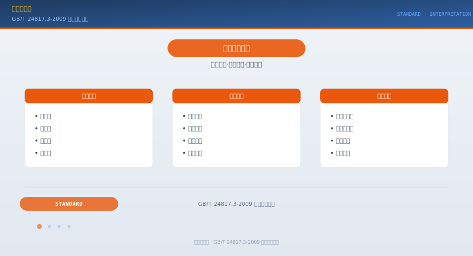
Tower Crane Control Device Layout & Operation Guide

GB/T 24817.3-2009 "Lifting Appliances — Arrangement and Characteristics of Control Devices — Part 3: Tower Cranes" is the dedicated standard governing control device layout for tower cranes. Recognizing the elevated positioning of the crane cab and the widespread use of remote control operation, the standard details layout requirements, operating direction characteristics, and remote control design specifications, corresponding to ISO 7752-3:1985 (MOD).

GB/T 24817.3-2009 is Part 3 of the crane control device arrangement series, addressing the specific control characteristics and operational requirements of tower cranes. It defines the layout and operating characteristics of control devices. A well-designed control layout is critical to safe work at height. The following sections break down the key requirements of the standard.

GB/T 24817.3-2009 tower crane control device layout


Standard Scope and Tower Crane Operating Characteristics

GB/T 24817.3-2009 corresponds to ISO 7752-3:1985 (MOD) and is the third part of the GB/T 24817 series. Tower crane operation differs significantly from that of ground-based cranes: the operator's cab is positioned high on the tower mast (typically 20–60 m above ground), and the crane is controlled either directly from the cab or via a remote control. The three primary mechanisms — hoisting, slewing, and luffing (via trolley or luffing jib) — are each operated by independent control devices. Unlike mobile cranes, tower cranes generally have no travel control (except for the crane travel function on rail-mounted tower cranes), so the controls are grouped into three functional clusters: hoist, slew, and luff. The standard tailors its layout and operating direction requirements to these characteristics.

Control Device Layout in the Operator's Cab

The standard specifies that control devices inside the tower crane cab be arranged as follows:

Hoisting Control — The hoisting control lever is positioned to the right of the operator's seat (right-hand operation). Operating direction: pulling back raises the hook (hoisting), pushing forward lowers it (lowering). The hoist controller must provide a sufficient number of steps (at least 4 for hoisting, 3 for lowering) to accommodate high-speed operation with light loads and low-speed operation with heavy loads. For tower cranes with Variable Frequency Speed Control, a single-lever proportional controller may be used for stepless speed regulation.

Slewing Control — The slewing control lever is positioned to the left or left-front of the seat (left-hand operation). Operating direction: pushing left slews the crane to the left (counterclockwise rotation), pushing right slews it to the right (clockwise), both referenced to the forward-facing cab position. The slew controller should include a slewing brake button (thumb-operated) and a free-slewing selector switch. Acceleration and deceleration of the Slewing mechanism must be smooth; the standard requires that the starting angular acceleration at the jib tip (50 m radius) not exceed 0.1 m/s² to prevent excessive load swing.

Luffing Control — For trolley luffing tower cranes, the trolley luffing control lever is typically positioned to the left of the seat (on the same side as the slewing control but separated vertically or horizontally). Operating direction: pushing forward moves the trolley away from the cab (increasing the working radius), pulling back brings it closer (decreasing the radius). For luffing jib tower cranes, the luffing control lever operates as follows: pulling back raises the boom (decreasing the radius), pushing forward lowers it (increasing the radius) — consistent with the hoisting direction logic.

Crane Travel Control — For rail-mounted tower cranes, crane travel control may be located on the cab control console or operated via a floor remote control. Operating direction: pushing the lever forward moves the crane forward, pulling it back moves the crane in reverse. Travel Limit Switches and buffer stops must be fitted at both ends of the travel stroke.

Hoisting Control
Right-hand operation
Pull back to hoist
Slewing Control
Left-hand operation
Push left/right to slew
Luffing Control
Left-hand, separate zone
Trolley / luffing jib
Remote Control
Floor operation
Hoist + slew + luff
Emergency Stop Button
One in cab, one on remote
Both must be fitted
Slewing Acceleration
≤0.1 m/s²
At jib tip

Radio Remote Control Requirements

Tower cranes — particularly small and medium-sized units — commonly use Radio Remote Control for floor operation. The standard sets out the following design requirements for the remote control: it must be equipped with at least three joysticks (or proportional handles), one for each of the hoisting, slewing, and luffing mechanisms, with operating directions consistent with those in the cab (the "direction consistency" principle). The remote control must include an Emergency Stop Button (a large red button that, when pressed, cuts off the crane's main power supply and requires manual reset), and two start buttons that must be pressed simultaneously with both hands to energize the system, preventing accidental activation. Communication between the remote control and the crane must use encrypted frequency-hopping technology to prevent interference and unintended commands. When the remote control battery is low, an Audible and Visual Alarm must activate, providing a warning for at least 5 minutes before complete power loss. The effective control range must be no less than 100 m in open areas; beyond this range, or in the event of signal loss, the crane must automatically stop all operations.

Display and Indicator Devices

The standard requires the following display devices on the tower crane cab control console: a Load Limiter display screen (showing actual load, rated load, and load percentage), a working radius display (showing current radius, jib length, and angle), a Height Limit Switch indicator (showing hook height status), and an Anemometer display (real-time wind speed and alarm status). Display brightness must be adjustable to suit varying daylight and nighttime conditions. In addition to visual alarms, an audible alarm device with a sound pressure level of no less than 85 dB(A) must be provided. Kelude Heavy Industry tower crane control consoles are ergonomically optimized, with right-hand hoisting and left-hand slewing, allowing operators to work for over 200 hours without fatigue.

Kelude Heavy Industry: Overhead Cranes & Gantry Cranes

Kelude Heavy Industry is a leading manufacturer of overhead cranes and gantry cranes, delivering reliable material handling solutions for industrial applications across the United States and Europe. Our product range covers single-girder and double-girder overhead cranes, gantry cranes, and explosion-proof crane systems, engineered to meet the highest standards of safety and performance.

Overhead Cranes Built for Heavy-Duty Performance

Our overhead cranes are designed for continuous operation in demanding environments. Available in capacities from 1 ton to 100 tons (0.9 to 90.7 metric tons), these cranes feature low-headroom configurations, variable-frequency drives for smooth load control, and optional anti-sway technology for precise positioning. All models comply with ISO 4301 and ISO 12480 standards, ensuring structural integrity and operational safety.

Model SeriesCapacity RangeSpan (ft / m)Key Features
QD5–50 tons (4.5–45.4 t)20–100 ft (6–30 m)Double-girder, hook or grab bucket, IP55 protection
LH5–32 tons (4.5–29 t)20–80 ft (6–24 m)Low-headroom, single-girder, electric hoist
LX1–10 tons (0.9–9 t)15–60 ft (4.5–18 m)Single-girder, suspension type, compact design

For specialized applications, we offer explosion-proof overhead cranes certified for hazardous areas (ATEX / NEC 500), with fully sealed electrical enclosures and non-sparking components. These cranes are widely used in chemical plants, oil refineries, and paint shops where flammable gases or dust are present.

Gantry Cranes: Versatile Solutions for Outdoor & Indoor Use

Our gantry cranes are engineered for flexibility, with options for rubber-tired or rail-mounted configurations. Capacities range from 5 to 300 tons (4.5 to 272 metric tons), with spans up to 150 ft (45 m). These cranes are ideal for shipyards, steel yards, precast concrete plants, and container handling facilities.

Model SeriesCapacity RangeSpan (ft / m)Application
MG5–50 tons (4.5–45.4 t)30–120 ft (9–36 m)General industrial, storage yards
ME50–150 tons (45.4–136 t)60–150 ft (18–45 m)Heavy fabrication, shipbuilding
MH1–20 tons (0.9–18 t)15–60 ft (4.5–18 m)Light duty, maintenance shops

All gantry cranes can be equipped with anti-sway systems, variable-frequency drives, and remote control operation. For outdoor installations, we provide galvanized or painted finishes with marine-grade protection, ensuring long-term durability in harsh weather conditions.

Electric Hoists & Trolleys for Precise Load Handling

Our electric wire rope hoists and chain hoists are designed for reliable performance with minimal maintenance. Available in capacities from 0.5 to 50 tons (0.45 to 45.4 t), these hoists feature self-locking brakes, thermal overload protection, and low-noise operation. Hoisting speeds can be customized to match your specific production requirements.

Hoist TypeCapacity RangeLifting Height (ft / m)Features
CD10.5–10 tons (0.45–9 t)20–60 ft (6–18 m)Single-speed, compact, low headroom
MD11–20 tons (0.9–18 t)20–80 ft (6–24 m)Two-speed, smooth start/stop
HC5–50 tons (4.5–45.4 t)30–100 ft (9–30 m)Heavy-duty, dual braking, IP55

For applications requiring precise load positioning, we offer variable-frequency drive (VFD) hoists with anti-sway control, enabling accurate placement even at high speeds. All hoists are factory-tested and certified to meet CE and ISO 4306 standards.

Custom Engineered Crane Solutions

Beyond standard models, Kelude Heavy Industry provides fully customized crane systems tailored to your facility layout and process requirements. Our engineering team works closely with you to design cranes with special spans, lifting heights, end carriages, and control systems. We also offer retrofitting services to upgrade existing cranes with modern safety features and automation capabilities.

Whether you need a single crane or a complete material handling system, our team delivers on-time, on-budget solutions backed by comprehensive after-sales support, including spare parts availability and remote diagnostics.

Frequently Asked Questions

Q: What is the lead time for a standard overhead crane?
A: For standard models (QD, LH, LX series), lead time is typically 4–6 weeks from order confirmation. Custom engineered cranes may require 8–12 weeks depending on complexity.

Q: Do you provide installation and commissioning services?
A: Yes, we offer full installation, commissioning, and operator training services in the US and Europe. Our technicians are certified and follow all local safety regulations.

Q: Can your cranes be integrated with existing plant control systems?
A: Absolutely. Our cranes support Profibus, Modbus, and Ethernet/IP interfaces, allowing seamless integration with your PLC or SCADA systems.

Q: What warranty do you offer?
A: All cranes come with a 24-month warranty covering parts and labor. Extended warranty packages are available upon request.

Q: How do you ensure crane safety compliance?
A: Our cranes are designed and manufactured in accordance with ISO 4301, ISO 12480, and IEC 60204-32 standards. Each crane undergoes rigorous load testing and inspection before shipment.

Q: Do you offer spare parts for older crane models?
A: Yes, we maintain an extensive inventory of spare parts for all models manufactured in the last 20 years. Contact our support team with your crane serial number for quick identification.

Q: Can you provide explosion-proof cranes for Zone 1/21 areas?
A: Yes, we manufacture explosion-proof cranes certified for Zone 1, 2, 21, and 22 hazardous areas, with options for ATEX or NEC compliance.

Q: What is the maximum span available for gantry cranes?
A: Our standard gantry cranes can achieve spans up to 150 ft (45 m). For special requirements, we can engineer spans beyond this with additional structural analysis.

Control Function Operation Mode Arrangement Position Direction Convention
Hoisting / Lifting joystick/Remote Control Lever Right Side of Seat Pull Back Push Forward
Slewing joystick/Remote Control Lever Left Side of Seat Push Left Push Right
Trolley Luffing joystick/Remote Control Lever Left Side of Seat(Layering) Push Forward Working radius Increase
Boom Luffing joystick/Remote Control Lever Left Side of Seat(Layering) Pull Back Working radius Decrease
crane travel Button/Joystick control console/Remote Control Push Forward Pull Back
Emergency Stop Red Mushroom-head Emergency Stop Button control console+Remote Control Press to De-energize

Safety and Emergency Control Systems

A: Tower cranes must be equipped with comprehensive safety controls and emergency devices. When a limit switch on any mechanism is activated, power to the hazardous direction of that mechanism must be cut off, allowing operation only in the safe direction. When the Overload Limiter is triggered (at ≥110% of rated load), hoisting up and luffing out must be stopped, accompanied by a continuous Audible and Visual Alarm. Pressing the Emergency Stop Button immediately halts all crane mechanisms—either by shutting down the engine (for diesel-powered units) or by disconnecting the main Power Supply contactor (for Electric models). For rail-mounted tower cranes, crane travel must be interlocked with Rail clamps and the travel motor: the travel motor cannot be started unless the Rail clamps are fully released.


Tower Crane Control Device Arrangement: Comparison Table

The comparison table below outlines the core Parameter configurations for the arrangement of control devices on tower cranes, serving as a reference for selection and operational personnel.

← Scroll left / right to view full table →
control deviceOperating Functionlayout requirementssafety protection
Hoisting / Lifting ControllerHook Hoisting/LoweringRight-hand Operating PositionNeutral Positioninterlock+Overload protection
Slewing ControllerTower Jib SlewingLeft-hand Operating Positionslewing limit Protection
luffing control DeviceTrolley LuffingLeft/Right-hand Sidelimit switch+anti-collision
Emergency StopMain Power ShutdownDirectly in Front of OperatorSelf-locking Manual Reset

Frequently Asked Questions

Q: Why are hoisting and slewing controlled by separate hands on a tower crane?
A: This design follows the ergonomic principle of dividing tasks between the two hands. Hoisting (raising and lowering the hook) and slewing (rotating the boom) are the two most frequent operations on a tower crane. Assigning each to a separate hand allows both actions to be performed simultaneously, boosting operational efficiency. The right hand controls hoisting, leveraging the majority of operators' fine-motor precision for speed and positioning accuracy, while the left hand manages slewing, capitalizing on the left hand's spatial orientation strengths. This left-right division has become the industry-standard control layout for tower cranes.
Q: How is safety ensured when operating a tower crane with a remote control?
A: Safety during remote-controlled tower crane operation is ensured through the following mechanisms: 1) Dual-button activation — both start buttons on the remote control must be pressed simultaneously to connect the power supply, preventing accidental activation when the unit is clipped to the operator's belt; 2) Signal encryption — frequency-hopping spread spectrum (FHSS) technology prevents signal interference between multiple tower crane remotes; 3) Signal-loss protection — if the remote signal is interrupted for more than 2 seconds, the crane performs an automatic stop of all motions; 4) Direct emergency stop — the emergency stop button on the remote control is wired through an independent safety relay that cuts the crane's main power supply directly, bypassing any logic controller; 5) The operator must position themselves where the load is directly visible around the crane while operating the remote control.
Q: Why is acceleration limiting required for tower crane slewing control?
A: During slewing, the load swings due to centrifugal force. If the slewing acceleration is too aggressive—such as with sudden starts or emergency stops—the load can swing significantly, with displacement reaching 5% to 10% of the jib-end horizontal travel. This not only compromises positioning accuracy but also risks the load striking the tower mast or adjacent structures. Standard requirements cap the jib-end linear acceleration at 0.1 m/s², which translates to an angular acceleration of approximately 0.002 rad/s² for a 50 m jib length. This limit ensures smooth acceleration and deceleration during slewing, keeping the load sway angle within ±3°.
Q: What special requirements apply to luffing control on a luffing jib tower crane?
A: Luffing operation on a luffing jib tower crane is subject to a "gravity-assisted" effect—when the boom is lowered, gravity accelerates it naturally. As a result, the lowering speed (boom descent) must be actively governed by the luffing mechanism brake rather than relying on free fall under gravity. Standard requirements mandate that the lowering speed of the luffing mechanism must not exceed 1.2 times the rated derricking speed under any load condition. The luffing wire rope system must incorporate a dual-rope redundant system, where either rope alone is capable of withstanding the full luffing tensile force in the event of wire rope breakage of the other. Luffing control must also be interlocked with radius limit switches (both upper and lower limits) and a load moment limiter (LML) for coordinated protection.

Related News

contact

contact us

phone:
+86 13903802779

mail:3915269@qq.com

Working hours: Monday to Friday

Wechat
Wechat
SHARE
TOP