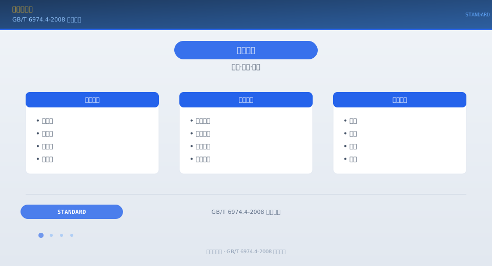
Jib Crane Terminology: ISO 4306 Terms & Definitions

GB/T 6974.4-2008 "Cranes — Vocabulary — Part 4: Jib Cranes" is the dedicated terminology standard for jib-type cranes. It defines the specific terms and definitions for jib cranes including portal cranes, mast cranes, floating cranes, deck cranes, cantilever cranes, and railway cranes, corresponding to ISO 4306-4:1995 (MOD).

GB/T 6974.4-2008 is Part 4 of the crane terminology series, specifically governing the terms and definitions for jib cranes.

GB/T 6974.4-2008 Jib Crane Terminology Standard


Standard Scope and Terminology Framework

GB/T 6974.4-2008 is the fourth part of the GB/T 6974 "Cranes — Vocabulary" series, dedicated to standardizing terminology for jib-type cranes. Jib cranes come in a wide variety of configurations with significant structural differences — from portal cranes to floating cranes to mast cranes — and each type has its own terminology system that shares common ground while retaining type-specific terms. The standard covers approximately 160 specialized jib crane terms across six categories: crane type, main structure, mechanisms and devices, safety devices, performance parameters, and operational terms. Standardized jib crane terminology is essential for technical communication and safety management in shipyards, ports, and heavy equipment installation sectors.

Jib Crane Type Terminology

The standard defines terminology for each jib crane configuration: Portal crane — a crane mounted on a gantry structure with a slewing jib system, allowing railway vehicles or road vehicles to pass through the portal base. Mast crane — a crane whose jib is mounted on a slewing mast (column) stabilized by guy ropes. Floating crane — a crane installed on a barge or pontoon, used for port loading/unloading and offshore lifting operations. Deck crane — a slewing jib crane mounted on a ship's deck for handling the vessel's own cargo. Cantilever crane — a fixed-base jib crane (wall-mounted or column-mounted) with a slewing jib at a fixed or adjustable working radius. Railway crane — a crane mounted on a railway vehicle chassis, capable of traveling and operating on rail tracks.

Portal Crane
Gantry + slewing jib
Vehicles pass underneath
Mast Crane
Guy-rope stabilized
Ground or deck mounted
Floating Crane
Barge/pontoon mounted
Port & offshore lifting
Deck Crane
Shipboard cargo handling
Slewing jib type
Cantilever Crane
Wall/column mounted
Short-radius duty
Railway Crane
Rail-chassis travel
Rescue / track laying

Main Structural Component Terms

The standard precisely defines the terminology for the main structural components of jib cranes: Portal base — the portal-shaped structure unique to portal cranes, comprising legs, cross beams, and diagonal struts, which carries the full load transmitted from the slewing platform above. Jib system — includes the main boom, the fly jib (where applicable), and the connecting tie bars or suspension ropes. Slewing platform — the rotating structural component that carries the jib, hoisting mechanism, luffing mechanism, and counterweight, connected to the base/portal via the slewing bearing. Counterweight — weights mounted at the rear of the slewing platform or on the balance arm to offset part of the load moment and reduce the overall overturning moment. Guy rope — steel wire ropes used on mast cranes to keep the mast stable, typically arranged with 4 or more ropes evenly spaced. Ground anchor — the fixing point for guy ropes, either buried in the ground or secured to counterweight blocks.

Mechanism and Safety Device Terms

The standard specifies terminology for jib crane mechanisms and safety devices: Luffing mechanism — the mechanism that changes the working radius of the jib (wire rope luffing / rack-and-pinion luffing / hydraulic cylinder luffing). Grab (grab bucket) — a double-jaw load-handling device for bulk cargo, operated by coordinated hoisting and closing drum action to grip and release material. Load moment limiter (LML) — a combined safety device that monitors both lifting capacity and working radius parameters (mandatory on jib cranes). Radius limit switch — a safety device that prevents the jib from luffing beyond the maximum or minimum allowable working radius. Anti-tipping-back device — a mechanical or hydraulic device that prevents the jib from tilting backward beyond its limit position under no-load or light-load conditions. Luffing speed-limiting valve — a hydraulic control valve in the luffing system that prevents excessive lowering speed. In Kelude technical communications, all jib crane technical characteristics are described using the standard terminology specified in GB/T 6974.4.


Jib Crane Terminology Classification Table

The comparison table below lists the core parameter configuration of the jib crane terminology classification, for reference by selection and operating personnel.

Kelude Heavy Industry: Overhead & Gantry Crane Solutions

Kelude Heavy Industry specializes in the design and manufacture of heavy-duty overhead cranes, gantry cranes, and electric hoists. Our equipment is engineered for demanding industrial environments, offering reliable performance, precise load control, and long service life. From standard models to fully customized solutions, we deliver material handling systems that boost productivity and safety across manufacturing, logistics, and energy sectors.

Frequently Asked Questions

Q: What is the typical lead time for a standard overhead crane?
A: For standard models, lead time is typically 6–8 weeks from order confirmation. Customized cranes may require 10–14 weeks depending on complexity.

Q: Do you provide installation services?
A: Yes, our technical teams handle installation and commissioning worldwide. We also offer operator training and maintenance contracts.

Q: Can your cranes be adapted for explosion-proof areas?
A: Absolutely. We supply explosion-proof cranes and hoists compliant with IEC 60204-32, suitable for Zone 1 and Zone 2 hazardous areas.

Q: What is the warranty period?
A: We offer a standard 12-month warranty covering parts and workmanship, with extended warranty options available upon request.

Q: Do you offer spare parts for older models?
A: Yes, we maintain a comprehensive inventory of spare parts for all Kelude models, including legacy systems. Contact us with your serial number for quick identification.

← Scroll left / right to view full table →
Term CategoryCore TermDefinition DescriptionCorresponding English
StructureBoom/portal frame/slewing platformLoad-Bearing and Slewing mechanismboom
LuffingLuffing mechanism/Luffing Tie barAlterationworking radiusluffing
SlewingSlewing Bearing/Slewing mechanismRotation Motionslewing
safety deviceLoad moment limiter (LML)/Anti-Tipping BackOverload Protectionsafety device

FAQ

Q: What is the difference between a "portal crane" and a "gantry crane" as defined in GB/T 6974.4-2008?
A: These two terms are often confused. A "gantry crane" (defined in GB/T 6974.5) is a crane whose bridge girder is supported on ground-level crane rails by outriggers — commonly known as a gantry crane. Its bridge girder remains horizontal, and the trolley travels along it to provide horizontal movement. A "portal crane" (defined in GB/T 6974.4) features a portal frame combined with a slewing boom structure. The space beneath the portal base allows passage, while the jib rotates around the slewing center to achieve full coverage of the working area. In short: on a gantry crane, the load moves in two dimensions beneath the bridge girder; on a portal crane, the load is positioned in three dimensions through boom slewing and luffing. These are two fundamentally different structural types.
Q: What is the relationship between the "overturning moment" and the "load moment" of a jib crane?
A: The load moment (M_l) is the product of the lifting capacity (Q) and the working radius (R), representing the moment exerted on the slewing center by the hoisted load. The overturning moment (M_o) is the net moment acting on the crane base or slewing bearing that tends to tip the crane over. It is calculated by adding the moment generated by the dead weight of the jib system to the load moment, then subtracting the stabilizing moment produced by the counterweight. The load moment is the dominant component of the overturning moment, typically accounting for 60%–80% of the total, while the moment from the jib system's dead weight is partially offset by the stabilizing moment from the counterweight. In crane design, the stabilizing moment must be at least 1.15 to 1.25 times the overturning moment (depending on operating conditions and load combinations) to ensure the crane remains stable and does not tip over.
Q: What are the different luffing methods used in jib cranes?
A: Per ISO 4306 definitions, there are three primary luffing methods for jib cranes: 1) Wire rope luffing — the boom angle is adjusted by reeling in or paying out the luffing wire rope via a winch. This method offers a simple structure but derricking speed is limited by wire rope service life, making it suitable for small-to-medium portal cranes and floating cranes. 2) Rack-and-pinion luffing — a gear-and-rack mechanism drives the boom, providing high stiffness and precise boom positioning. This is well suited to large portal cranes. 3) Hydraulic cylinder luffing — the boom angle is changed directly by extending or retracting a hydraulic cylinder, delivering a compact structure and flexible control. This method is commonly found on mast cranes and certain smaller portal cranes. Each approach has its own trade-offs; the final selection should be based on lifting capacity, derricking speed, and accuracy requirements.
Q: What is a "boom anti-tilt device" and why is it required?
A: An anti-tilt device is a dedicated safety device on jib cranes. When the crane is in a no-load or light-load condition, the combined dead weight of the counterweight and jib system can cause the boom to tilt backward past its maximum working radius—a condition known as back-tilting. This can result in the boom striking the tower mast or gantry structure, potentially causing severe structural damage or even collapse. Anti-tilt devices come in two types: mechanical (limit stops, buffer springs) and hydraulic (cylinder locking). As the boom approaches its maximum radius, the anti-tilt device automatically engages to prevent further rearward movement. During daily inspections, verify that the anti-tilt device functions properly and that its limit switch positions are accurately set.

Related News

contact

contact us

phone:
+86 13903802779

mail:3915269@qq.com

Working hours: Monday to Friday

Wechat
Wechat
SHARE
TOP