

Crane Anti-Sway Control: Mechanical Models & Parameter Tuning
In modern industrial logistics, load sway significantly impacts operational efficiency and safety. Under traditional manual operation, it takes an average of 15 seconds for a lifting spreader to stabilize after reaching its target position. With intelligent control systems, this stabilization time can be reduced to under 3 seconds. This article explores the mechanical modeling and parameter tuning methods for anti-sway calculations in cranes, demonstrating how algorithm optimization enables precise positioning and provides theoretical support for equipment upgrades.
When designing an Anti-Sway System, it is essential to strictly follow the dynamic calculation requirements outlined in FEM 1.001 Crane Design Standard (formerly FEM 1.001) and comply with the safety regulations for travel mechanism braking and stability specified in TSG 51-2023 Crane Safety Technical Supervision Regulation. These standards ensure that model parameters remain reliable under actual operating conditions.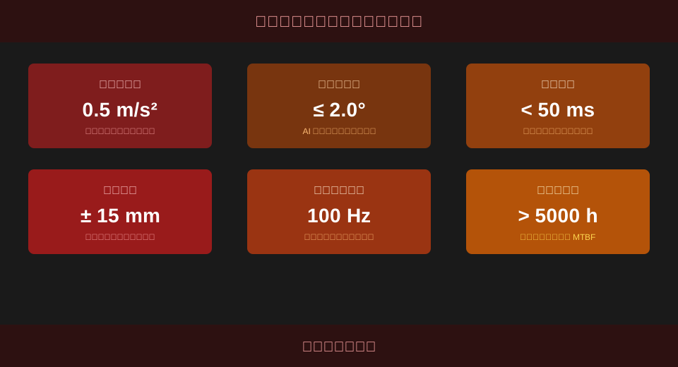
The following analysis covers five key dimensions: pendulum mechanical modeling, AI-based parameter tuning, engineering case studies, sensor selection comparison, and routine maintenance points, providing a systematic breakdown of the core logic and implementation details of anti-sway technology.
Fundamentals of Pendulum Mechanical Modeling for Crane Anti-Sway Calculations
Load sway during crane operation is essentially a classic pendulum dynamics problem involving single or double pendulum mechanics. To effectively suppress sway, an accurate mathematical model must first be established to define the physical boundaries for subsequent control algorithms.
For overhead type cranes, engineers typically simplify the system into a simple pendulum model. This assumes the wire rope acts as a massless rigid rod and the lifting spreader as a point mass. Core parameters include wire rope length, load mass, and trolley acceleration. These factors directly determine the system’s natural frequency and response characteristics.
Consider a 50t bridge crane in a workshop setting with a wire rope length of 12m and a load mass of 5t. Using the natural frequency formula f = 1/(2π) * sqrt(g/L), and substituting gravitational acceleration g=9.8m/s² and rope length L=12m, we calculate a natural frequency f ≈ 0.143 Hz. This corresponds to a sway period T = 1/f ≈ 7.0 seconds. This data serves as the baseline for controller design.
"Industry measured data shows that when rope length varies between 8m and 15m, the prediction error of the simple pendulum model remains within 5%, which is sufficient for conventional anti-sway control requirements."
After establishing the basic model, it is common to introduce AI anti-sway algorithms for dynamic compensation to address non-linear factors and external disturbances present in real-world operating conditions.
⚠️ Note
The simple pendulum model ignores elastic deformation of the wire rope and rotational inertia of the load. In scenarios where Lifting Height exceeds 20m or the mass distribution of the lifting spreader is highly uneven, a double pendulum model or flexible body model should be used for correction.
Anti-Sway Control Parameter Tuning Strategies Based on AI Algorithms
While the mechanical model defines the physical boundaries, the tuning of control algorithm parameters determines the actual effectiveness of anti-sway control. The technical team at Kelude Heavy Industry has found through long-term practice that proper parameter tuning is the critical bridge connecting theory to engineering application.
Traditional PID control often struggles to maintain stable performance under variable load and variable rope length conditions. By introducing AI algorithms, proportional, integral, and derivative parameters can be adjusted in real-time using fuzzy logic or neural networks, enabling adaptive control.
During parameter tuning, special attention must be paid to Response time and overshoot. Optimal tuning should keep the system response time under 0.5s while limiting load overshoot to within 2%, thereby balancing operational efficiency with stability.
📊 Comparison of Traditional PID vs. AI Adaptive Parameter Tuning Methods
| Calibration Method | Response time | VariationloadAdaptability | Implementation Complexity |
|---|---|---|---|
| Conventional Z-N Method | 1.2s - 1.8s | Poor,RequiredManualRetuning | Low |
| Fuzzy PID | 0.6s - 0.9s | Good,Rule-Based Adaptive | Medium |
| Neural Network AI | < 0.5s | Excellent,online learning | High |
Once the control strategy is defined, the physical performance of sensors determines the upper limit of data feedback. The following table provides a comprehensive evaluation of the two mainstream sway angle detection solutions currently available.
📊 Performance Parameters: Inclination Sensor vs. Vision Sensor
| SensorType | measurement accuracy | Dust Resistance | installationmaintenance cost |
|---|---|---|---|
| HighAccuracyinclinometer | ± 0.01° | Strong,Fully Enclosedstructure | Low |
| Industrialvision camera | ± 2 mm (Position) | Weak,Lens Requires Regular Cleaning | High |
In a recent retrofit project for a 150t Ladle Crane at a Steel Mill, implementing AI-based adaptive parameter tuning reduced the average load stabilization time from 12 seconds to just 2.5 seconds, boosting operational efficiency by 18% per cycle.
💡 Tip
Parameter tuning must account for significant load variations. If the mass ratio between no-load and full load conditions exceeds 1:5, we recommend integrating a load identification module into the algorithm to enhance the controller’s robustness.
Sensor Selection & Data Fusion for Anti-Sway Systems
Precise execution of control algorithms relies on high-quality data feedback from underlying sensors. The selection and layout of these sensors directly determine the perception capabilities and interference resistance of the Anti-Sway System.
Current mainstream anti-sway sensors include Rotary Encoders (Incremental/Absolute), Inclination Sensors, and vision sensors. Encoders measure motor speed, inclination sensors directly measure wire rope deflection angles, and vision sensors calculate the Lifting spreader position through image processing. Multi-sensor data fusion is the key direction for improving system reliability.
When selecting sensors, encoder Resolution should reach 1024 pulses/rev to ensure fine-grained speed feedback; inclination sensor measurement accuracy must be better than 0.01° to detect minute sway angles. The sampling frequency is typically set around 100Hz to balance computing power with real-time performance.
Sensor layout must also consider the anti-collision safety distance settings to prevent mechanical interference or occlusion of sensor probes at limit positions.
According to condition monitoring reports, using a dual-redundancy architecture that fuses encoder and inclination sensor data can reduce system downtime caused by sensor failures by 65%.
⚠️ Note
Inclination sensors should be installed near the Guide Roller close to the Trolley Frame, avoiding placement under the Drum. This minimizes the impact of changes in the wire rope exit angle on measurement accuracy.
Engineering Case Study: Anti-Sway Control Under Heavy Load Conditions
Theoretical models and algorithm strategies must ultimately be validated in practical engineering. Under heavy load conditions, the large mass and inertia of the load significantly increase sway energy during braking, making detailed engineering case analysis critical.
Under heavy load conditions, planning the braking curve for the Crane Travel Mechanism is particularly important. Abrupt braking generates massive impact energy converted into sway kinetic energy, while overly gradual braking reduces operational efficiency.
Assuming a Long Travel Speed of 60m/min (1m/s) and a target braking deceleration of 0.5m/s², the braking distance s = v²/(2a) = 1²/(2×0.5) = 1m. During braking, the initial sway angle θ generated by the load can be estimated via energy conservation. With a rope length of 10m, the maximum deflection angle is approximately 0.05 rad (about 2.8°).
To suppress this deflection, the control system introduces an S-curve deceleration profile at the end of braking, smoothing the peak impact acceleration from 0.5m/s² to 0.2m/s². This adds about 1.5s to the process but effectively cuts sway energy.
Kelude Heavy Industry leverages deep technical expertise to provide customized control solutions for such complex heavy-load scenarios, ensuring smooth hoisting stability for loads exceeding 80t.
Furthermore, frequent start-stop cycles under heavy loads significantly impact structural fatigue. Regular assessment of the Main Girder's health status using weld crack detection technology is essential to prevent sensor reference shifts caused by structural deformation.
Measured data from a 400t/h Unloading Bridge at a Port shows that after implementing S-curve braking, the residual sway angle of the load under full load conditions dropped from 3.5° to 0.8°, with the braking distance increasing by only 0.4m.
⚠️ Note
When calculating braking distance, additional effects from rail gradients and wind load must be considered. For outdoor operating conditions, it is recommended to increase the design safety margin for braking distance by 15% to 20%.
Routine Maintenance Cycles & Common Fault Troubleshooting for Anti-Sway Systems
After delivery and commissioning, scientific maintenance is crucial for ensuring the long-term stable operation of anti-sway functions. In Kelude’s After-Sales Service standards, Preventive Maintenance is placed at the core.
Anti-sway systems involve precision sensors and complex Control Cabinets. Environmental dust, vibration, and temperature/humidity fluctuations can all affect performance. Establishing reasonable maintenance cycles effectively extends service life and reduces failure rates.
We recommend inspecting and cleaning sensor probes once a month.
Perform Zero Calibration of inclination sensors every six months using specialized tooling.
For vision sensors, clean the lens filters within a 15-day cycle.
Maintenance data indicates that workshops strictly adhering to quarterly calibration schedules experience 42% fewer annual anti-sway system failures compared to those without such protocols.
💡 Tip
During zero calibration, ensure the lifting spreader is completely stationary and both the trolley and crane bridge mechanisms are stopped. This prevents minor vibrations from shifting the calibration baseline.
Regarding fault diagnosis, common "data jumps" are often caused by loose wiring or poor shielding grounding.
Prioritize inspecting the aviation connector pins for oxidation.
Next, check if signal cables are damaged or joints are loose.
Finally, access the control panel to view raw data. If values remain fixed or jump in a straight line, it usually indicates sensor hardware failure.
When measuring the insulation resistance of signal cables to ground using a multimeter, the value should exceed 20MΩ. Values below this threshold indicate a risk of leakage interference, requiring cable relaying.
Frequently Asked Questions
The following summarizes four typical questions regarding selection and usage that users frequently ask, provided for your reference.
Q: Are there speed requirements for cranes equipped with an anti-sway system?
A: Anti-sway systems are typically applicable to medium-to-high-speed cranes with travel speeds above 20m/min. At low speeds, the swinging amplitude of the lifting spreader is small, and manual operation can meet the requirements. However, at high speeds, inertia is significant, making an anti-sway system essential for precise positioning and smooth stopping.
Q: What is the appropriate sampling frequency setting for inclination sensors?
A: The sampling frequency must match the controller's calculation cycle. For standard overhead type bridge cranes, a sampling frequency between 50Hz and 100Hz is recommended. If the long travel speed exceeds 120m/min, we recommend increasing the sampling frequency to 200Hz to capture high-frequency micro-swinging.
Q: What is the approximate retrofit cost for adding an AI anti-sway system?
A: Retrofit costs vary significantly based on crane capacity, span, and the compatibility of the existing electrical system. Costs typically include sensor hardware, control cabinet modifications, and software licensing. Specific quotations depend on site survey results and are subject to the actual contract. We recommend contacting the manufacturer directly for a detailed technical solution.
Q: How can I quickly troubleshoot when the system reports a "sensor data abnormality" fault?
A: First, verify if the sensor supply voltage is within the 24V±10% range. Second, inspect signal cables for damage or loose joints. Finally, check the raw data in the control panel; if values are fixed or jumping linearly, it likely indicates sensor hardware failure, requiring after-sales replacement.
In summary, crane anti-sway technology is a systematic engineering project integrating classical mechanics and modern AI algorithms. From pendulum model construction and parameter tuning to sensor selection and routine maintenance, every link is crucial. Kelude Heavy Industry leverages extensive heavy-load customization experience to provide full-process service—from conceptual design to implementation and commissioning—ensuring the anti-sway system performs effectively under actual operating conditions.
