Tower Crane Limiters & Indicators: ISO 10245-3:2008 Explained

ISO 10245-3:2008, "Tower Cranes — Limiters and Indicators," is the dedicated international standard governing safety devices on tower cranes. It specifies the technical requirements and test methods for load moment limiters (LML), lifting capacity limiters, radius limiters, height limit switches, and slewing limiters.


Load Moment Limiter: Technical Requirements

ISO 10245-3:2008 sets out the technical requirements for the load moment limiter (LML) on tower cranes. The LML must monitor the load moment across all jib length and working radius combinations. When the moment reaches 90% of the rated value, an audible and visual alarm is triggered (buzzer ≥85 dB plus flashing red indicator light). At 100% of the rated moment, the limiter automatically stops hoisting and luffing-out operations, while still permitting lowering and luffing-in. The LML accuracy requirement is a combined error of ≤±5% over an ambient temperature range of -10°C to +55°C, with sensor zero-point drift limited to ≤±0.1%/°C.

Tower crane LMLs have specific requirements that differ from other crane types. They must accommodate variable jib lengths and multiple operating configurations, automatically switching between load curves based on the current jib length and tower height. All LML settings — including the rated lifting capacity curve, jib length parameters, and safety factors — must be protected by password protection or a locking mechanism to prevent unauthorized modification. The data recording function must store at least 500 overload events (time, moment value, and action taken), with data retention of ≥10 years after power loss. The LML display must be mounted on the operation panel in the operator cab, showing the lifting capacity, working radius, and moment percentage.


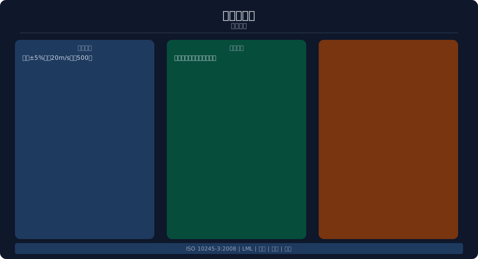
Standard interpretation diagram


Radius Limiter and Height Limit Switch Requirements

The radius limiter restricts the trolley's maximum and minimum working radius positions. On horizontal jib tower cranes, the minimum radius is set at ≥3 m from the tower mast centerline to prevent the trolley from striking the mast, while the maximum radius is limited to ≥1 m before the jib tip. Radius measurement uses an encoder or laser distance measurement, with an accuracy of ±1% or ±0.1 m. When the trolley reaches the limit position, the luffing motor automatically stops (luffing power is cut), allowing the operator to reverse the trolley out of the limit zone. The hoisting height limit switch operates in two stages: the first stage issues an early warning when the hook is 1 m from its highest position, and the second stage automatically stops hoisting and triggers an audible and visual alarm when the hook is 0.3 m from the highest position.

The slewing angle limiter is used in applications where the slewing angle must be restricted, such as when the crane operates near buildings or high-voltage lines. It issues an early warning within ±2° of the set angle and stops slewing when the limit angle is reached. Once the slewing limit is triggered, reverse slewing is permitted. The anemometer must be mounted at the highest point of the crane (on the tower top or jib tip). When wind speed reaches the set working wind speed limit (typically 20 m/s, corresponding to Beaufort scale 6), an early warning is issued. When the extreme wind speed limit is reached (typically 27 m/s, Beaufort scale 8), the crane automatically stops operations and sounds an alarm.

LML Accuracy
±5%
Warning Threshold
90% of Moment
Limit Threshold
100% of Moment
Overload Log
≥500 Events
Wind Speed Warning
20 m/s
Wind Speed Shutdown
27 m/s
safety device Function Setpoint Alarm Mode Actuator
Load moment limiter (LML) Torque Monitoring Protection 90%early warning/100%Stop Audible and Visual Alarm Cut-off Hoisting / Lifting Amplification
Radius Limiter Trolleylimit switch minimum/Maximum radius Audible and Visual Alarm Stop Luffing Motor
Height Limit Switch Hooklimit switch -1mearly warning/-0.3mStop Two-stage Alarm Cut-off Hoisting / Lifting
Slewinglimiter Slewing anglelimit switch Setting±2° early warning Stop Swing Motor
Anemometer Wind Speed Monitoring 20m/searly warning/27m/s Stop Audible and Visual Alarm Machine Shutdown

Testing & Inspection Requirements

The standard specifies both type tests and factory inspections. Type tests cover accuracy verification — measurements taken three times at 25%, 50%, 75%, 100%, and 110% of rated load, with a combined error of ≤±5% — along with durability testing (LML system operating continuously for ≥1,000 hours without failure), environmental testing (16-hour exposure to 60°C high temperature and -20°C low temperature, followed by functional and accuracy checks; vibration testing from 5 to 200 Hz), and electromagnetic compatibility testing. Factory inspections are performed unit by unit and include functional checks (early warning, limiting, and self-check functions operating correctly), accuracy verification at 50% and 100% of rated load moment, and alarm system checks.

Periodic inspection requirements — after tower crane installation and commissioning, the LML system must be calibrated (load curve set according to the actual jib configuration). System calibration is required every six months using standard test weights or force sensors. Calibration records for the LML system must be retained with the crane's documentation. Recalibration is mandatory after any sensor repair or replacement. Kelude tower cranes are equipped with LML safety systems configured to ISO 10245-3:2008, with type tests and factory inspections completed before delivery.


Routine Maintenance & Fault Handling

The standard defines routine maintenance and fault handling requirements for the LML system. Daily inspection items: verify the LML panel display is functioning properly (parameter values appear reasonable), confirm the self-check buzzer sounds once on startup, and check sensor signal cables for loose connections or damage. Monthly maintenance items: verify LML accuracy using standard test weights (recording calibration results), inspect sensor mounting conditions, and clean sensors and junction boxes. Common fault handling — abnormal display: check sensor power supply and signal cables; accuracy out of tolerance: recalibrate the system; alarm not activating: inspect the alarm device and controller.

Correct configuration of LML software parameters — particularly the rated lifting capacity curve — directly affects safety protection effectiveness. Users must not modify system parameters on their own. Whenever the jib length is changed or the anchored height is adjusted, qualified personnel must reconfigure LML parameters and recalibrate the system. Kelude provides installation, commissioning, calibration, and maintenance services for tower crane LML systems.

maintenance item Period Operator content requirements
Daily Inspection Per Shift operator Panel Display/Self-test Tone/Connection Cable
Accuracy Calibration Monthly Maintenance Operator Standard Weight Calibration±5%
Sensor Inspection Quarterly Maintenance Operator Fixing/Connection Cable/guards
System Calibration Semi-annually Specialist Technician Full Measuring Range+Sensor
Parameter Setting Boom Length Change Qualified Personnel Load Curve Reset

FAQ

Q: What special requirements apply to the tower crane load moment limiter?

A: The tower crane LML must accommodate variable boom lengths and multiple operating conditions, automatically switching load curves based on the current boom length and tower height. Parameter settings are password-protected, and the system stores at least 500 overload events. Combined error is within ±5%. Kelude Heavy Industry's tower crane LML system features intelligent load curve switching.

Q: Where should the anemometer be installed and what are the alarm thresholds?

A: The anemometer is mounted at the highest point of the tower crane (on the tower top or boom tip). An audible and visual early warning is triggered at 20 m/s (approx. 6 on the Beaufort scale), and the crane automatically stops operation at 27 m/s (approx. 8 on the Beaufort scale). If the wind exceeds the cut-off limit, the boom must be released before the operator leaves the crane.

Q: What is the calibration interval for tower crane safety devices?

A: Calibration is performed once after installation and commissioning, followed by a system calibration every 6 months using standard test weights or force sensors. Parameters must be reconfigured after any boom length change or anchored height adjustment. Recalibration is required after maintenance or sensor replacement. Calibration records are retained with the crane's documentation.

Q: What are the alarm and limit values for the LML system?

A: An audible and visual early warning (buzzer ≥85 dB plus flashing red light) is activated when torque reaches 90% of rated capacity, and hoisting and radius increase are automatically stopped at 100%. The lifting capacity limiter independently stops hoisting when the load reaches 105% of rated capacity. A pre-alarm (operator attention) is given at 75% of rated capacity.

Related News

contact

contact us

phone:
+86 13903802779

mail:3915269@qq.com

Working hours: Monday to Friday

Wechat
Wechat
SHARE
TOP