

How to Calculate Overhead Crane Hoisting Motor Power
📐 Calculation Overview
The core of hoisting motor power calculation is the static power formula P=Q×v÷(6120×η): P is the motor static power (kW), Q is the total lifting load (kgf, including the dead weight of the lifting spreader), v is the lifting speed (m/min), and η is the total efficiency of the mechanism. The total efficiency is the product of three stages — reducer, drum, and pulley block — and it is the variable most often guessed at rather than calculated.
This formula is used for preliminary motor rated power selection under steady-state, constant-speed hoisting conditions, covering wire rope hoist mechanisms on bridge cranes and gantry cranes. Starting acceleration verification, braking verification, and thermal verification must be calculated separately on top of this. This article provides the methods and a complete worked example. It does not apply to direct-drive, VFD constant-power, or other special transmission configurations.
Take the same 50-ton bridge crane: choose a lifting speed of 3 m/min or 8 m/min, a total efficiency of 0.85 or 0.90, and the static power formula spits out results ranging from roughly 27 kW all the way to 77 kW — nearly a threefold difference. That gap isn't about any particular piece of equipment; it comes down to different boundary conditions and how you assign values.
FEM 1.001 Crane Design Standard treats hoisting mechanism calculation as the first step in overall crane design, and hoisting motor power calculation is the stage most prone to error. Once you understand the logic behind three variables — total efficiency, lifting speed, and work duty classification — power calculation stops being guesswork.
Five Boundary Conditions to Lock Down Before Motor Power Calculation
The first step in hoisting motor power calculation isn't plugging numbers into a formula — it's locking down the boundary conditions. Change the boundary conditions, and the same crane can yield two completely different motor power ratings.
There are five boundary conditions, and each one directly determines the final power.
① Lifting load — rated lifting capacity plus the dead weight of the lifting spreader. Hook blocks and wire rope typically account for 2%–5% of rated capacity, and this is the most commonly overlooked component.
② Lifting speed — for 50t–300t European Standard double-girder cranes, lifting speed typically falls between 2 and 8 m/min. The higher the capacity, the lower the speed. Every 1 m/min change in speed shifts static power by roughly 15%–25%.
③ Work duty — the difference in thermal verification conversion between M5 and M7 can reach 30%, making it the most easily ignored variable. FEM 9.311 Classification of Mechanism Duty divides mechanisms into multiple levels based on frequency of use and load spectrum. You must confirm this level before selecting a motor.
④ Transmission chain configuration — pulley ratio, number of reducer stages, and drum diameter together determine the total efficiency value.
⑤ Power supply and duty classification — Cyclic Duration Factor (CDF) and hoisting duty classification determine the conversion method for thermal verification.
At Kelude Heavy Industry, on 50t–300t European Standard double-girder projects, these five boundary conditions are confirmed item by item and written into the design calculation report during the design input stage, preventing repeated power revisions downstream.
Breaking Down the Static Power Formula: Why Total Efficiency Can't Be Guessed
The static power formula for a hoisting motor is written as P=Q×v÷(6120×η), where Q is the total lifting load (kgf), v is the lifting speed (m/min), η is the total mechanism efficiency, and P is in kW.
The origin of the constant 6120 is worth explaining. 1 kW is approximately equal to 102 kgf·m/s. Converting speed from m/s to m/min requires dividing by 60, so 102×60=6120. This constant is simply the result of unit conversion — not an empirical coefficient.
The real challenge lies in determining total efficiency η. It isn't the efficiency of any single component but the product of three stages: reducer efficiency × drum efficiency × pulley block efficiency.
Three-stage hardened gear reducers typically achieve 0.93–0.95 efficiency; planetary reducers can reach 0.96–0.98. Wire rope drum efficiency is about 0.94–0.98. Pulley block efficiency varies with pulley ratio — roughly 0.95–0.97 for ratios of 2 to 8. Multiply all three, and total efficiency lands between 0.85 and 0.90.
The most common mistake in the industry is simply plugging in 0.9 or 0.85. At Kelude Heavy Industry, European Standard projects assign values to the reducer, drum, and pulley block individually before multiplying, because differences at each stage get amplified in the final power figure.
Complete Verification Example: 50-Ton European Standard Double-Girder Hoisting Motor
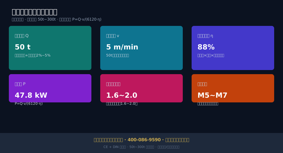
Here is a complete walkthrough of static power calculation using a 50-ton European Standard double-girder crane hoisting mechanism from Kelude Heavy Industry. This unit has a lifting speed of 5 m/min, a lifting spreader dead weight taken as 3% of rated capacity (1.5 tons), and a total lifting load of approximately 51.5 tons.
Plugging into the formula: P=51500×5÷(6120×0.88)≈47.8kW. The total efficiency of 0.88 corresponds to the product of a three-stage hardened gear reducer at 0.94, drum at 0.97, and pulley block at 0.96.
Calculating static power is only the first step. The motor rated power must pass three more checks.
① Starting verification — starting torque must reach 1.6–2.0 times rated torque to ensure smooth full-load startup without stalling.
② Thermal verification — convert static power to equivalent power according to M7 duty classification (60% CDF), confirming that winding temperature rise stays within the allowable limit for Class B insulation.
③ Standard power rating rounding — 47.8kW rounds up to 55kW in the standard power series, leaving approximately 15% safety margin.
Following this process, the selection result goes from "somewhere around 50kW" to a definitive conclusion: "static power 47.8kW, rated power 55kW, starting and thermal verification both passed."
Three Common Mistakes in Hoisting Motor Selection
Hoisting motor selection failures rarely come from formula errors — most come from skipping one of the three checks. Three of the most common mistakes deserve separate discussion.
The first mistake is oversizing. Some buyers habitually select a larger motor, assuming extra margin can't hurt. In reality, an oversized motor has lower efficiency at light loads, more concentrated heat generation, greater starting impact, and unnecessary added cost. The key to power matching is precise calculation, not arbitrary padding.
The second mistake is calculating static power only without thermal verification. Under frequent lifting conditions, actual motor heat generation far exceeds the temperature rise corresponding to static power. A motor that skips thermal verification will burn out its windings within a few months.
The third mistake is ignoring work duty conversion. M5 and M7 operating conditions place very different thermal demands on the motor. Selecting a motor for a M7 crane using M5 criteria plants a long-term hidden risk.
The technical director at Kelude Heavy Industry pointed out: "A hoisting motor isn't better just because it's bigger. An oversized motor actually has lower efficiency at light loads. The key is to calculate all three checks — static power, starting verification, and thermal verification — clearly."
Safety supervision imposes additional requirements on hoisting mechanisms. TSG 51-2023 Crane Safety Technical Supervision Regulation requires hoisting mechanisms to have reliable braking and limit functions, and motor selection must match the crane's safety protection devices.
| Parameter | Symbol | typical value | Value Description |
|---|---|---|---|
| lifting load | Q | 50~300 t | IncludingLifting spreaderDead Weight 2%~5% |
| Lifting Speed | v | 2~8 m/min | capacityLargerspeedLower |
| Reducer / GearboxEfficiency | η1 | 0.93~0.95 | Three-stagehardened tooth flank |
| DrumEfficiency | η2 | 0.94~0.98 | Wire Rope Drum |
| sheave block efficiency | η3 | 0.95~0.97 | Pulley Ratio 2~8 |
| mechanismTotal Efficiency | η | 0.85~0.90 | Product of Three Stages |
| Conversion Constant | — | 6120 | 1 kW≈102 kgf·m/s |
| MotoroverloadCoefficient | K | 1.6~2.0 | starting torqueverification |
| Lifting Capacity | Lifting Speed | Total Efficiency | StaticPower(Approx.) |
|---|---|---|---|
| 50 t | 5 m/min | 0.88 | 46 kW |
| 75 t | 4 m/min | 0.87 | 56 kW |
| 100 t | 3.5 m/min | 0.86 | 67 kW |
| 150 t | 3 m/min | 0.85 | 87 kW |
| 200 t | 2.5 m/min | 0.84 | 97 kW |
| 300 t | 2 m/min | 0.83 | 118 kW |
The static power values in the table are calculated examples based on the formula (excluding spreader dead weight and starting safety margin). Actual power requirements are governed by the design calculation report and contract.
📖 Related reading: How to Match Power, Speed, and Operating Conditions: Hoisting Motor Selection Logic for Cranes | Eliminating the Gearbox: What Makes Permanent Magnet Direct Drive Motors Superior for Cranes
FAQ
Q: Which standard does the static power formula for hoisting motor power calculation come from?
A: The static power calculation for hoisting mechanisms is primarily based on the mechanism design provisions of FEM 1.001 Crane Design Standard. The formula P=Q×v÷(6120×η) is the industry-standard steady-state equation. From a safety supervision standpoint, the hoisting mechanism must also comply with TSG 51-2023 Crane Safety Technical Supervision Regulation regarding braking and limit switch requirements. For European Standard (EN) projects, Kelude also cross-references FEM 9.311 mechanism classification group for power conversion.
Q: What are the symptoms of an undersized hoisting motor power selection?
A: The most typical symptoms of insufficient power are a noticeable drop in speed during heavy-load lifting, excessive motor heating, and frequent overcurrent or overload faults from the VFD. To diagnose the issue, compare the actual lifting speed under full load against the rated speed, and monitor whether the winding temperature exceeds the allowable limit for Class B insulation. For cranes above 50 tons, if frequent low-speed crawling or starting difficulties occur, the static power should be recalculated and a thermal verification performed.
Q: Why can hoisting motor power vary by nearly double across manufacturers for the same 50-ton crane?
A: The power difference comes primarily from three variables. Total mechanism efficiency between 0.85 and 0.90 accounts for roughly a 6% difference. A lifting speed of 5 m/min versus 3 m/min creates a 40% difference. The thermal verification difference between mechanism classification group M5 and M7 can reach 30%. For the same 50-ton crane, static power calculated under different boundary conditions can range from approximately 30kW to 77kW. This is not corner-cutting — it reflects different design boundaries. Buyers should require manufacturers to provide a complete calculation report.
